Showing posts with label Communication. Show all posts

Thursday, March 5, 2015

Serial Port Communication with GNU Octave in Windows

This is not so much a finished post as it is a place to record progress. Use any information found on this page at your own risk.

Introduction

I have been using GNU Octave in place of MATLAB on my laptop for a while now. It is free and serves my purposes well. One place MATLAB does have it beat though is in its ability to communicate with outside hardware through a serial port. I recently needed this functionality for Octave. This is how I made it work. My configuration:
  • Windows 7 - 64 bit
  • GNU Octave 3.8.2-5 using MXE installer
  • Instrument Control Package 0.2.1

Walkthrough

Install Octave

If you found this post I will assume you are probably running Windows. There is a convenient unoffical installer for Windows HERE. At the time of this writing I am running 3.8.2-5. Anything greater than 3.8.0 has the nice MATLAB style GUI.

Install Instrument Control Package

The equivalent of MATLAB toolboxes are packages in Octave. You need the instrument-control package to access the serial ports. There are two ways to install it.

1) Install it from Octave forge. Assuming you have an internet connection, open Octave and type in the command window "pkg install -forge instrument-control-0.2.1.tar.gz" Replace the 0.2.1 with the newest version of the package.

2) Download it from HERE. Assuming you did a standard install, move it to the folder "C:/Octave/Octave-3.8.2/src". There you will find all the other packages that were included with the installer. Now open Octave and make that folder your directory. Type in the command window "pkg install instrument-control-0.2.1.tar.gz". Obviously you may need to change the name of the package if you download a newer version.

Both options will take a while. One of my first mistakes was thinking I had crashed my computer. I wasn't sure if it would work on Windows, so when it just sat there for a minute I thought it was hung. Just give it some time. Mine took a couple minutes. 

Load Instrument Control Package

You only have to install the package once, but you need to load it every time you open Octave (you can also set it to auto load. Google it.)

Type "pkg list" to see all your installed packages. If you don't see instrument-control then you need to go back to the last step. Any package with an * by it is loaded.

To load the package type "pkg load instrument-control". Now load the list of packages again to see if it worked.

Use the Package

Now the part you have been waiting for. It is important to note that at the time of this writing the instrument control package is not a drop in replacement for the serial capabilities of MATLAB. Here are some helpful links to illustrate this. It is fairly obvious that the function names are different or missing for Octave.
For my initial test I used an Arduino with a jumper between Rx and Tx. This essentially mirrored anything I sent back to me. To simplify things, go to the device manager and change the serial port number to COM1 through COM8. Over that and additional work is needed. Device Manager > your port > Port Settings > Advanced > COM Port Number.

My Additions
To better serve my needs I added a few files to make the package more MATLAB compatible. Just make sure they are in your path somewhere if you want to use them.

srl_fwrite: Download HERE. Similar to the MATLAB fwrite. The regular srl_write only accepts char and uint8s. I made this function to simplify sending other variable types. Accepts three inputs 
  • Serial Object
  • Data to be sent
  • Data Type - int8, uint8, int16, uint16, int32, uint32, int64, or uint64
srl_fread: Download HERE. Similar to MATLAB fread. Reads serial port and returns data type specified. Takes three inputs.
  • Serial Object
  • Number of values to be returned. (eg for 3 uint64s, enter 3 not 24)
  • Data Type - int8, uint8, int16, uint16, int32, uint32, int64, or uint64

Test Script
Test Script: This script was taken and modified from the wiki linked above. It opens a serial port, sends a couple values and then attempts to read them when the serial device mirrors them back. A "correct" output should look something like this.

Serial: Supported
s1 = 0x444
int8 = 200
intdata =

    0  142    1   44


That is all I have at the moment. I hope this tutorial was useful to someone out there. I plan to do another post on the way I am actually using this capability in the future as a more in depth example. 

-Matthew

Thursday, January 9, 2014

I2C HC-SR04 Sonar Module: ATtiny85 I2C

In this post I will show you how to cheaply  make an I2C sonar sensor for your Arduino. This will be accomplished by making an I2C controller for an HC-SR04 sensor out of an ATtiny85 (or ATtiny45). Both the sensor and the microcontroller can be found online for a few dollars. Together these two parts can save you money while increasing functionality over premade solutions.

If you have not already done so, check out my previous post on a serial sonar sensor. It also discusses running the NewPing library on an ATtiny (my modified TinyNewPing library). I have also done a post on I2C communication. In fact, I even transmitted data from my PING sensor! Check it out HERE.

1) First off, we need an I2C library for your ATtiny. For this you have a few options, but I will only be using one of them. The regular Wire library will not work on the ATtiny side. However, thanks to some great work  by Arduino users BroHogan and Rambo we do have the TinyWire library. The original library by BroHogan can be downloaded HERE. I have used the Master library from it, but for the Slave library I will be using a fork by Rambo. He added a bit more functionality including an onRequest and an onReceive function (which I use in my examples). Find his library HERE (download zip link is in the bottom right corner).

You will also need the ATtiny core for whatever Arduino IDE you are using. In the past I have used the core from High-Low Tech. Now however I prefer the Google Code core. A recent update allows ATtiny support with Arduino 1.5. Anyway, if you need more details on getting an ATtiny running see my previous posts linked above or click on the ATtiny label.

You need to burn your ATtiny85/45 to 8MHz. This is important for stable I2C communication (consider making my ATtiny programming adapter!). You also need my TinyNewPing library installed.


2) Wiring is simple. Connect the 5V from the Arduino to the VCC of the ATTiny and the PING sensor. Connect all the grounds together. Then connect the Trigger and Echo pins of the PING sensor together and to pin 3 (PB3) of the ATtiny85. Next connect the I2C wires. Connect the ATtiny SCL (PB2) to the Arduino SCL (Arduino Uno: A5 , Arduino Mega2560: 21 , Arduino Due: 21). Connect the ATtiny SDA (PB0) to the Arduino SDA (Arduino Uno: A4, Arduino Mega2560: 20 , Arduino Due: 20). Finally, and very importantly, connect 4.7k (on 5V) ohm pull-UP resistors to the SCL and SDA lines.


3) Now you have the libraries installed. Everything is wired up. The only thing left to do is test it. THIS code goes on the ATtiny. It reads one HC-SR04 sensor and acts as the I2C slave. THIS code goes on your other Arduino. I used a Mega, but you can use whatever you have. It requests the data from the slave and then outputs it to the serial monitor.

That is about it. Assuming everything works, you are ready to go. Using this method, you should be able to get sensor data from many sensors at once using only 2 pins on your Arduino. One thing to remember, since they are not all being controlled by the same Arduino, the sensors are not synchronized. As such, they could interfere with each other if they are pointed in the same direction.

Also, I attempted to control multiple sensors with one ATtiny. This worked, sort of. It was buggy and crashed after 15 seconds or so, I suspect do to a I2C buffer issue. Regardless, it made the code more complicated on both sides and the system wasn't as reliable. Besides (I said to myself), ATtinys can be found fairly cheap (especially surface mount ones). My time is worth something. While I got tired of messing with it, if someone else gets it working let me know. I'd be interested to see your code.

There you have it. A cheap I2C ultrasonic ranger for an Arduino (or I2C master device of your choice). If you use this approach in any of your projects I would love to hear about it in the comments. Of course, if you have problems I will do my best to help you with them.

-Matthew

Wednesday, November 20, 2013

Homemade PPM Encoder

This project is a spin off from my PPM decoder project. The overall goal is to translate the individual PPM signals from an RC receiver (like THIS one) into usable data that can be sent via serial, I2C, or a simple analog pin. Breaking that down, we get three smaller goals. If you have no idea what I'm talking about, read up on the subject HERE.
1) Combine the different channels into one "PPM Stream"
2) Decode this stream using a microcontroller
3) Do something useful with this decoded information

This post will tackle the first issue. To decode the signals coming from the RC receiver we first want to combine all the different channels (e.g. aileron, rudder, elevator...) into one channel. We want to do this so that later we can decode all the channels with one hardware interrupt (a single pin). 

Before you begin, you should consider your different options
1) Buy a PPM encoder ($25) - This seems to be the most popular one. There are a few others floating around Ebay
2) Buy a receiver with a PPM Stream output - Various receivers have this functionality. There have also been reports of people using satellite receivers like THIS. I can neither confirm nor deny the feasibility of that.
3) Hack your existing receiver - Funny enough, your receiver probably has the signal in the form we want at one time or another. It then decodes it to separate out the channels for the different servos. If you can find the correct place to solder on a wire, you're in business. HERE is a great write up on this. I preferred a noninvasive approach.
4) Make your own external PPM Encoder- Read on!

Now, there are several ways you can make your PPM encoder. The most complicated way is described HERE. If you choose to go that route, I will forgive you. I have no doubt that it probably is more robust and "correct" than the way I am going. The schematic is included as well as the PCB gerber files, so if you have access to all the materials have at it.

The method I am using is pretty simple. Put a diode on each channel with a pull down resistor at the end. The schematic is below.


Note that the receiver is running at a 3.3V logic level. For some microcontrollers this is not a problem; the Arduino DUE operates at 3.3V logic. However, for a standard Arduino like the Uno or Mega2560 operating at 3.3V is flaky. While it may work, fluctuations could cause glitches. At any rate, I included a built in 3.3V to 5V logic level converter circuit.

The circuit consists of 4 resistors and 2 transistors. I based mine off of the circuit found HERE. It is worth noting that there are other ways to convert 3.3V logic to 5V. I am not qualified to explain all of them, but I can say that ready made solutions are available from many different vendors.

When you combine these two circuits, the following schematic emerges.


Running a quick LTSpice simulation on it yields the graph below. Note that blue is the output on the 5V side. Red is the input on one of the channels (in real life this will be digital, but I just did a voltage sweep from 0 -3.3). Green is the voltage at the 3.3V output. Note the slight voltage drop. While this is insignificant when using the logic level shifter, it is something to note if you are using a 3.3V microcontroller.


Now to assemble it.

Bill of Materials:

  • 1 - Protoboard
  • 9 - Male Headers 
  • 6 - 1N4148 Diodes
  • 2 - 2N3904 NPN Transistor
  • 3 - 1k Ohm Resistor
  • 1 - 10k Ohm Resistor
  • 1 - 1.5k Ohm Resistor

1N1418 Diode Array

Finished Product

Underneath Side

The keen eyed observer may spy that I substituted a 1k resistor for the 1.5k, and it works fine. I didn't have a 1.5k. You may also notice that it could be made a bit smaller with a little effort. That will be work for v2. 

On the finished product picture above, the six male headers are the six 3.3V inputs. The two male pins the the right are the 5V and GND connections. The single male header at  the bottom is the 5V encoded output. Below is a picture of it connected up to my Arduino Mega 2560 and 6 channel OrangeRx receiver.


Here are the results. The first picture is the signal when all the pins of the receiver are just straight wired together. The second picture is when the signals are run through my encoder without the logic level converter.The third is the full encoder output with the logic level converter. The main difference is the peak voltage. Without the encoder, each peak is about 500mV. With the encoder, each peak is about 4.9V. All three circuits are on channel 1 on the oscilloscope. See the scale in the bottom left of the oscilloscope screen.
Without Encoder
Encoder Without Logic Level Converter Circuit
Full PPM Encoder Output
As you can see, the encoder works perfectly. Each signal is distinguishable from every other signal and is large enough to be read by an Arduino. It is ready to be fed into one of the Arduino's hardware interrupts to be decoded. To decode the RC receiver signals go to my other post, Arduino PPM Decoder: Decoding an RC Receiver with an Arduino.

Let me know if this works for you! If you have problems, comment below and I will do my best to help you. 
Matthew

Arduino PPM Decoder: Decoding an RC Receiver with an Arduino

In this post I will detail how to decode the PPM signals from an RC receiver using an Arduino. Specifically, I will decode the signals from a 6 channel OrangeRx receiver using an Arduino Mega 2560 r3 and my custom PPM encoder board that I describe HERE.

As most interested people know, the only good way to do this is with interrupts. While pulseIn will work for a few channels, more than 2 or 3 will bog it down too much to do anything useful.

Step 1
Access PPM Stream. THIS site describes what I mean by that. In short, we want to combine the single signal from the six individual pins into six signals on an individual pin. This allows us to decode all 6 channels with one hardware interrupt. That's something any Arduino can handle.

Like I mentioned above, you will need my PPM Encoder to do that (there are other options that I discuss in that post as well). Luckily, it is fairly cheap and easy to make. You may ask, "Why can't I just wire all the pins together?" In short, it doesn't work. I tried. This is because when one pin is high, five are low. Again, more details are in my other post.

6 Channel PPM Stream

Step 2
Decode the PPM Stream. As you can see in the picture above, the PPM stream consists of six spikes that we need to decode. Now, there are many descriptions online about how to decode these signals using interrupts, but I wanted a hardware independent approach. I didn't want to have to worry about my timers not working when this code is running or anything like that. For that reason, I wrote some fairly simple code that runs right in the Arduino sketch (vs tucked away in a library). I just set a hardware interrupt that triggers from a rising signal and subtract the times between each. (Read more on interrupts HERE). This of course causes a problem for channel 6 which doesn't have a signal coming after it. For this reason we have to do a few other things when we get to channel six.

HERE is my code. Look at it for yourself. It reads the values from the RC receiver, scales them to 1-100 and then prints them to the Serial Monitor. I'm not entirely happy with the way that I handled channel 6 at this point, but it works fine. I initially tried getting its value inside Spike(), but the micros() function does weird things inside it. I may revisit my approach someday, but it works for now. Though I wouldn't put anything life threatening on channel 6 (or any of the channels for that matter..). Below is an example output.


There you have it. A simple Arduino PPM signal decoder. Now you can get inputs from virtually any RC receiver and use them in your projects, library free. Hopefully you found this useful. As always, if you have any problems comment below and I'll see if I can help. If you had success, great! I'd love to hear about that as well. If you like this post, check out some of my others by clicking on a label that interests you.

Best of luck,
Matthew

Saturday, November 16, 2013

iRobot Create - Arduino interface cable

This post details the construction of a custom Arduino interface shield and cable for the iRobot Create. See my tutorial series on the iRobot Create. This cable allows the user to easily and cleanly interface with the Create and communicate with it via the Arduino Mega2560's Serial1 port.

Parts List:

Assembly is fairly self explanatory when you see the pictures. Here are a few useful charts.

Arduino Mega PinCreate Cargo Bay Pin
TX1 (pin 18)RXD (pin 1)
RX1 (pin 19)TXD (pin 2)
GNDGND (pin 14)

The chart above shows the connections that must be made. Note that Serial0 on the Arduino cannot be used without additional external hardware.


Cargo Bay Pinout.JPGArduinoMega pinout.png
First things first, assemble the protoshield as per THESE instructions.

Next, solder the ribbon cable to the DB25 connector. I chose to do it in such a way that the pins would be mirrored on both end. Note the way the ribbon cable connectors work, every other wire is connected to the top row. Really, the only important thing is that you include pins 1, 2 and a ground. Crimp the ribbon cable connector on.

Now you need to solder on some male headers to the protoshield. This is where the ribbon cable will connect.

Connect the male header that corresponds to the ground to the ground pin on the Arduino. Use the colored wire to make a jumper that will go from the RXD and TXD pins to the Arduino TX1 and RX1 pins respectively (in the picture below, it is the black and white wire in the bottom center).

Note that Serial1(TX1/RX1) must be used on the Arduino Mega (the Uno will not work without external hardware). The serial port output TXD from the Roomba/Create is too weak to drive the RX serial port (Serial0) input of an Arduino properly. This is because of the USB-Serial converter on the Arduino: it also tries to drive the RX serial port input via a pullup resistor, but the Roomba does not have enough drive to pull the RX down below about 2.5 volts, which is insufficient to be reliably detected as a TTL serial input of 0. Furthermore, using Serial1 still allows for the use of the Arduino Serial Monitor for debugging purposes. Also note that Serial2 or Serial3 could be used if selected in software.

Test your board and see if it works!

I hope this post was somewhat useful. It isn't so much of a how to as it is a description of what I did. There are many ways to do it. Really, the only important thing is that you connect TXD to RX1, RXD to TX1, and GND to GND. When you do that, you'll be ready to head back to my tutorial series!

Matthew

Friday, October 18, 2013

Simple Face Tracking with OpenCV, myrobotlab GUI, and Arduino

In this post I will detail how to easily use OpenCV with an Arduino to detect and track a face. There are many methods out there, but this method gives you the best OpenCV GUIs that I have seen. Vision processing is never simple, but I think you will be pleasantly surprised.

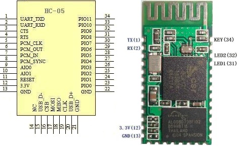
First things first, I would probably get a lot more Google hits if my title said install OpenCV on Arduino. Many wayward Arduino users have traveled that road only to feel a little foolish when they realize just how impossible that is. An Arduino doesn't come close to cutting it in terms of processing power. There is a project porting OpenCV to a rasberrypi, but that is a different post. What we will be doing is using a computer to process video from a connected camera and then send the useful data to an Arduino in the form of (x,y) coordinates via serial. This is cool because it means that your Arduino can be connected via Bluetooth or USB and can do other things while the computer handles the heavy lifting.

The program that I will be using is called myrobotlab (MRL). I go into more detail in my Intro to myrobotlab post, but basically it is opensource, free, and in active development. When I set out to find an easy, GUI enabled OpenCV platform, this is what I found. While I have not done a full out comparison to ROS or RoboRealm, my general impression is that ROS is quite a bit more complicated, and RoboRealm is quite a bit more expensive (MRL is free). Regardless, you want a simple OpenCV, Arduino system. Let's go get one.

First you need to install myrobotlab. See the Quick Start section for instructions. Make sure you get the right version of Java. I seem to remember having some problems with that. If you do, post a comment or ask GroG on the site. I'd also recommend that you go ahead and create an account on myrobotlab.org. If you need help or have a question, that's where you need to be.

Next open MRL by clicking on the batch file and go to the runtime tab. Here you'll find a list of all the services MRL currently has to offer. Go ahead and scroll down to OpenCV. Right click on it to download and install it.

Then right click on it again and click start. It will want you to give it a name. Call it whatever you want. You do this so you can have multiple instances of the same service open if you want to.

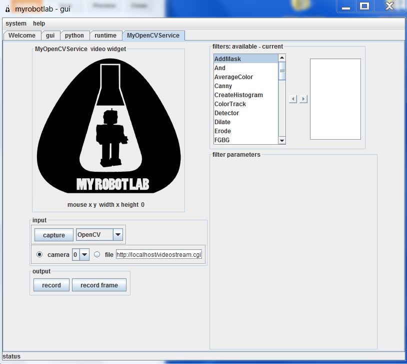
Now you are come to the OpenCV GUI. It will default to camera 0. If you have multiple cameras connected, this might not be the one you want. Click capture to see what camera you have selected, and find the one you want.

Now we need to add our filters. First you need to scroll through and select PyramidDown. Either right click and add or select and hit the right arrow. Give it whatever name you want. PyramidDown makes the video smaller (you'll see). FaceDetect is pretty processor heavy, and unless you have a monster work station you'll want to use it. It will actually increase performance.

Next add the FaceDetect filter. Now click capture and go to town. You should see video in the box and a box drawn around any face. This is a good time to play around. The majority of the filters can be accessed through the GUI. See what filters help you isolate the face(or whatever you are trying to track). Try multiple PyramidDown filters or an InRange filter. Also note that if you right click in the display window, it will give you the coordinates in pixels. This is useful behavior.

Now I hit you with the bait and switch. It's not nice and GUI all the way to the end. Reason being, you need another service (the serial service) to actually get the data from your nice OpenCV box to your Arduino board. This requires you to use the python service.

The code really isn't that bad. I knew no python when I started working with myrobotlab. I still know very little, but I have pieced stuff together well enough from example sketches. You can look at the sketch below, but I would recommend you download it HERE.


# This code creates an opencv service and tracks a face.# It thens finds the center of the face and converts the position to a scale of 1-100# This information is then sent via serial service to any receiving device
# If the script needs to be restarted, completely close MRL and reopen it.# 8/27/13
import time
from java.lang import Stringfrom java.lang import Classfrom java.awt import Rectanglefrom org.myrobotlab.service import Runtimefrom org.myrobotlab.service import OpenCVfrom org.myrobotlab.opencv import OpenCVDatafrom com.googlecode.javacv.cpp.opencv_core import CvPoint;from org.myrobotlab.service import OpenCV
# create or get a handle to an OpenCV serviceopencv = Runtime.createAndStart("opencv","OpenCV")
# Convert the video to Black and Whiteopencv.addFilter("Gray1", "Gray")                             # Sometimes gray seems to help# reduce the size - face tracking doesn't need much detail. The smaller the fasteropencv.addFilter("PyramidDown1", "PyramidDown")# add the face detect filteropencv.addFilter("FaceDetect1", "FaceDetect")

#create a Serial service named serialserial = Runtime.createAndStart("serial","Serial")
# This function is called every time the OpenCV service has data available.# This will depend on the framerate of the video, but will probably be# somewhere around 15 times a second.def input():    global x    global y    global sposx    global sposy    global posx    global posy
    # Get OpenCV data    opencvData = msg_opencv_publishOpenCVData.data[0]
    if (opencvData.getBoundingBoxArray().size() > 0) :    # If the box surrounding a face exists     rect = opencvData.getBoundingBoxArray().get(0)       # Store the information in rect     posx = rect.x                                        # Get the x position of the corner     posy = rect.y                                        # Get the y position of the corner
     w = rect.width                                       # Get the width     h = rect.height                                      # Get the height     sposx = (w/2)     sposy = (h/2)     # Get the x and y of the center in pixels. Origin is in top left corner     x = (posx + sposx)
     y = (posy + sposy) 
     # Convert x,y pixels to (x,y) coordinates from top left.     # Note that 320 and 4240 will need to be changed if another pyramid down is used     # It may also need to be changed depending on your cameras specifications.     # This gets the position in a scale from 1, 100     x = int(translate(x, 1, 320, 1, 100));                  # translate() works the same way the Arduino map() function would     y = int(translate(y, 1, 240, 1, 100));     print 'x: ' ,  x                                        # print x to the python readout     print 'y: ' ,  y                                        # print y to the python readout     #write a series of bytes to the serial port     serial.write(250) # pan code     serial.write(x)   # x coordinate     serial.write(251) # tilt code     serial.write(y)   # y coordinate
 
#connect to a serial port COM15 57600 bitrate 8 data bits 1 stop bit 0 parity#This is what you want for an Arduino. Change the COM port to the one you are using.serial.connect("COM15", 57600, 8, 1, 0)#sometimes its important to wait a little for hardware to get readysleep(1)          # Note that this is 1 full second.
# create a message route from opencv to python so we can see the coordinate locationsopencv.addListener("publishOpenCVData", python.name, "input");
# Start capturing videoopencv.capture()  # Add a 1 inside the parenthesis to use camera 1


# Create function to scale values. Mimics Arduino map() function.def translate(value, leftMin, leftMax, rightMin, rightMax):    # Figure out how 'wide' each range is    leftSpan = leftMax - leftMin    rightSpan = rightMax - rightMin
    # Convert the left range into a 0-1 range (float)    valueScaled = float(value - leftMin) / float(leftSpan)
    # Convert the 0-1 range into a value in the right range.    return rightMin + (valueScaled * rightSpan)


Copy that into the python window and you're almost done. Towards the end you need to change the COM port to the one you are using. Below that, you will see opencv.capture(). If you are using a camera other than camera 0, put that number in the parenthesis.

Now connect your Arduino and click execute. You will see several readouts in the java window. The last one you should see should say
[opencv_videoProcessor] INFO  org.myrobotlab.opencv.VideoProcessor  - using com.googlecode.javacv.OpenCVFrameGrabber
That means you made it to the bottom of the script and you are getting video.

This is what is happening. The OpenCV service applies 3 filters: Gray, PyramidDown, and FaceDetect. It gets a box around the face and passes the coordinates in pixels to the python service. The python service finds the center of the box and the converts the pixel coordinates to a scale of 1-100 with the origin in the top left with positive down and to the right. The python service then passes the coordinates to the Serial service which connects to your COM port and begins sending x, y values across. It sends an identifier, then the value in the order below. Both the identifier and the coordinate are 1 byte in length.
  • 250
  • x coordinate
  • 251
  • y coordinate
What you do with those values on the Arduino side is up to you. That is why I used the serial service. It enables you to plug this system up to an existing Arduino project or any existing Arduino sketch and get vision processing data with nothing more that a Serial.read() and some if statements. Best of all, it is all in Arduino C, so anyone that has learned to program on an Arduino (like myself) can deal with the complicated stuff in a language they already know using the libraries that they already know.

I chose to make a pan-tilt camera mount that follows people, but like I said above, what you do with those (x,y) coordinates is really up to you. If you need help with serial communication, see my posts HERE and HERE. If you just want my pan-tilt Arduino code get it HERE. If you want the detailed description... wait until I write that post.

That's all I have. I plan on doing more specific examples in the future. For now, this should get you started. For more examples look at my labels. The one's labeled myrobotlab or vision processing will be the ones to check out. 

I hope this is of use to someone. I really do think myrobotlab is one of the best free, simple GUI system for OpenCV out there. It is fairly easy to use, and the support is great (just post on the site and ask for help). When I began using it, there was no serial service. I asked for one, and within a week GroG had added one.Who could ask for more?

Goodluck! May your frame rates always be high and your visions always be processed.
-Matthew

Tuesday, September 3, 2013

Receiving Serial Data with an Arduino

In this post I will demonstrate a few ways to receive data via serial on an Arduino from a computer. I received a question about this on one of my other posts and decided to make a post on this topic.

First off, read the official Arduino documentation on this HERE. You may very well not need this after you do.

Second, there are some official Arduino examples that come with the IDE. I won't replicate something that is already there.

Third, if this is not what you are looking for (perhaps you were looking for serial between 2 Arduinos). Check my labels. There is one called communication that might interest you. Now let's get to it.

I'm going to assume you already know how to send data to your computer. It isn't hard to get pretty things to pop up on the Serial Monitor. If not, check out the serial examples under basics in the IDE.

To send data from the Serial Monitor you need only type something into it and hit enter. Most terminal emulators probably work the same way.

Get my Serial Test sketches HERE. I will just comment on the methods from the Flash_the_LED sketch. It was made for a previous post but will work just fine for this. You send it a number from the Serial Monitor and it flashes the LED that many times.

while (Serial.available())
This is the first important part of the sketch. This is a pretty typical scenario. You only want to check for new values when there is something in the Serial buffer. If there is nothing, Serial.available() will return 0 and the statement will be false. Remember 0 is false. Anything else is true.

val = Serial.parseInt();
This part receives 2 bytes from the serial buffer and converts them back from ascii to the number you want. If you are using a terminal emulator and are having problems, this might be it. I believe the Serial Monitor puts it through an ascii conversion, but other programs might not.

An int value is made up of 2 bytes in ascii format. That is why you need the parseInt(). If you are just receiving one byte, just use Serial.read(). That receives one byte. You can also piece bytes together yourself and do individual bits in a byte, but that is another post. That should about cover it for this topic.

Serial communication can get complicated, but the basics are simple on an Arduino. Play around with it. Look over the Arduino examples and MINE. Hang out on the Arduino playground and forum. You will soon be an Arduino communication master.

Matthew

Wednesday, August 7, 2013

Serial Sonar Sensor: ATtiny85, HC-SR04, and Arduino SoftwareSerial

In this post I will detail how I used an ATtiny85 as a controller for an HC-SR04 sonar module (Ping sensor). The controller reads the inputs from up to 3 HC-SR04 modules and transmits the readings to an Arduino Mega via serial communication. This allows the Arduino Mega to pick up the readings whenever it is convenient rather than having to worry about complex timings. Let's get started


First things first, we need to run the NewPing library on an ATtiny85/45/25. Until version 1.6 is released you will need to modify the library to do this. However, this removes some of the functions you might want to use on other boards. For this reason, I created the TinyNewPing Library. In it, I removed the parts that cause the errors on an ATtiny and gave it a new name so you can distinguish between the two. All the function names remain the same. If you still need more details check out THIS prior post.

Next we need the SoftwareSerial Library on the ATtiny. Luckily, this comes with the IDE and I already did a post on it. Funny how that works.

For a first attempt, try a single HC-SR04 sonar sensor. This simplifies the code a bit. Load THIS code on the ATtiny (sensor side) and THIS code on the Arduino Mega. Note the code uses both Serial and Serial1 (thus the Arduino Mega).

To wire it up, connect the echo and trigger pin together and then connect them to pin 0. Wire in 5V and ground to both the ATtiny and the HC-SR04. Then connect pin 4 (Software Tx) on the ATtiny to pin 19 (Rx1) on the Mega. Finally, plug the Mega into the computer via USB.

Now if this is working ok, we can move on to 3 sensors. For that, we need to load THIS code onto the ATtiny and THIS code onto the Arduino Mega. The ATtiny takes the readings and sends them to the Mega. The Mega updates it's variables and sends them to the Serial Monitor for us to see.

Wiring it is cumbersome but simple. Regrettably, I did not take a picture when I did it, but just do what you did before an extra two times. Note again that we are using the same pin for trigger and echo, so they need to be wired together. Then wire up power and grounds. Finally connect the ATtiny to the Mega and the Mega to the computer.

Now open the Serial Monitor and watch the numbers scroll by.

Potential problems: If the ATtiny gets out of sync with the Mega (it will), an occasional bad value will come up. I couldn't come up with a quick fix for this. If that is a problem, maybe you could take the median of a few readings. They are coming in pretty quickly. The plan is to make an I2C version of this soon, but I make no promises on a deadline. One last download, get the entire package of sketches used in this post in a zip file HERE.

A few quick notes before we go.

  • Why not I2C? That's next (Done! Check it out HERE). Serial is easier because it doesn't require a 3rd party library to work on the ATtiny line. 
  • Why only 3 sensors? Short answer, ease of use. You might be able to get 4 or even 5 out of an ATtiny45 if you're persistant. I don't have that many sensors nor that much patience. You have 5 regular IO pins plus the reset pin (which can be used as an IO). You might be able to use the serial Rx pin as an input as well. 
  • Why not just buy a I2C ping sensor and be done with it? Well this reduces the number of wires going to the Arduino Mega. It also gives you more options and increases the number of micro controllers on board your robot (cool factor). Other than that, it's cheap. With HobbyKing or Ebay, this project could be done for less than the price of one I2C sonar sensors.
Hopefully someone will find this useful. If anything goes great, please comment! If anything goes wrong, contact your local internet service provider. I blame them (That's a joke. You can comment below as well).

-Matthew

Thursday, June 13, 2013

Serial Communication on a ATtiny85 with the SoftwareSerial Library.

"Serial is giving me errors on my ATtiny! What can I do?" We have a solution.

Serial communication is not difficult on an ATtiny thanks to the SoftwareSerial Library. While the ATtiny85 does not have the hardware of a "real" Arduino, it can still function in similar fashion. If you're just getting started with using an ATtiny, here are some resources you might need.

  • Information on programming them from High-Low Tech. You can also look back at my previous posts.
  • My nifty programming adapter. A few minutes of soldering made my life much easier.
  • My USBtinyISP is discussed in THIS post. It also makes life easier.
  • Previous posts on Running Servos and the NewPing Library on an ATtiny.
  • THIS previous post mentioning my USB to UART converter cable
Now we are ready to go. First things first, I am using Arduino 1.0.4. The SoftwareSerial Library is included as a default library, so there is no reason to get a 3rd party library.


Step One: Wire it up. With my USB to UART cable it is as follows.
  • Black: Ground
  • Green: Tx (using Tx as pin 4)
  • White: Rx (using Rx as pin 3)
  • Red: 5v (this is optional if you have an external power supply)
Connect an LED with appropriate resistor to pin 1.

Step Two: Ensure that your ATtiny is burned to run at 8MHz. Now load THIS sketch onto the ATtiny. Note that parseInt() works with the SoftwareSerial Library.

Step Three: Open the Serial Monitor and set it to the correct Baud rate. To reset the ATtiny, bridge the reset pin to ground momentarily. When you see the connected message, enter an integer and count the flashes.

That's all there is to it. I you don't have a USB UART cable, this is easily adaptable to communication with another Arduino with a USB port. See THIS post for code. If you want to see a practical application of serial communication on an ATtiny85, check out my serial sonar controller HERE.

Hope this works for you all. As usual, if there are any questions, just let me know.
-Matthew

Tuesday, June 11, 2013

Multiple Simultaneous Serial Communications

As I mentioned in an earlier post I have an Arduino Mega with a broken USB to serial chip. With that in mind, I thought it would be useful to have an external USB to UART cable. Mine was $4 on Ebay. When it arrived I set to work ringing it out to make sure it worked. Here are the results.

Because my "broken" Arduino is still on my robot, I just used my working one. It is a supposedly identical Arduino Mega 2560 R3. As I played with this I realized that I could communicate with 2 ports simultaneously now (or 3 if I broke out my Bluetooth again). Why is this useful? It's not at the moment. This is really pretty simple, so this will be a short post.

Step One: Wire it up. With my cable it is as follows.

  • Black: Ground
  • Green: Tx (using Tx1 pin 18)
  • White: Rx (using Rx1 pin 19)
  • Red: 5v (this is optional if you have an external power supply).
It is worth noting that my cable does not allow for auto reset. This means that it is pretty difficult to load new programs to the Arduino with the default bootloader. 

Step Two: Load program on Arduino. This very simple. HERE is my example. When you're done, leave the USB plugged in.

Step Three: Open the Serial Monitors and watch for the messages. You will either need to use another program like Tera Term as mentioned in THIS post, or you can open two windows of the Arduino IDE.

That's all there is to it. Now you can communicate with the computer via two serial ports "simultaneously." If you need more information on Serial communications check out THIS post. I also have a post on I2C communication as well as Bluetooth.

-Matthew

Friday, June 7, 2013

Arduino Bluetooth with a HC-06 and JY-MCU

With the arrival of my Bluetooth module I decided to give wireless communication another try. I'm glad I did. Setting up my Bluetooth module for wireless communication took less than an hour. While I have not explored it very in depth yet, I can see myself getting some use from this module. It becomes a generic wireless COM port. I have even read about uploading sketches via Bluetooth if you use a custom bootloader. I will probably never delve into that, but let's get started with the basics.

When I first ordered my Bluetooth module, I got a "Bluetooth Serial Transceiver Module Base Board with Enable function For Arduino" from Ebay. I payed a few dollars for it only to realize when I got it that the board was merely a breakout (called a JY-MCU) for another board. Another purchase later, and I had all the things I needed to get going. I got an HC-06 (aka "New Mini 3.3V wireless Bluetooth Transceiver Slave Module Serial Port 30ft TTL"). There is also an HC-05 which apparently is very similar (it seems to share the same pinout).


HC-05 pinout
First things first, I soldered my HC-05 onto the JY-MCU. These can be purchased already soldered for less than $10, but the soldering was good practice. I held the module in place with double sided tape and a piece of tape around the end while I soldered it. The contacts aren't too small, but you will need a decent soldering iron with a small tip.
My impressive soldering


Next I wired it up. This is the point where I began calling on the collective knowledge of the internet. Follow THIS Instructable. With a few changes, it is what I did. For the voltage divider I used a 2.2k Ohm and a 1k Ohm + 100 Ohm resistor. It worked fine. I checked it with the volt meter and it came out to about 3.1v. HERE is the voltage divider calculator I used. Be sure you use that on the Bluetooth Rx/ Arduino Tx side or else you could fry your Bluetooth module. The ATmega 2560 will accept 3.3v so the Arduino Rx is fine by itself (sort of. I wouldn't put this on anything too important, but worst you will get false data). Someday I'll get a real logic level converter. For convenience, I used the Serial1 pins on my Arduino Mega 2560.

Now you need to load a test sketch onto your Arduino. I used the one on the Instructable (with Serial changed to Serial1). To do this you will probably need to unplug the Arduino Rx pin. Should we have loaded the program before wiring like the Instructable said? Probably. Oh well. Take this opportunity to double check all wiring and ring them out with a volt meter.

Now we need to connect the HC-06 Bluetooth module to the computer. I am running Windows 7, and this took about 3 minutes. The steps are on the Instructable, but I would feel bad if I didn't post all the screenshots that I took. Power up your Bluetooth module and follow the steps below.

1) Find the Bluetooth Icon in the bottom right hand portion of the screen. Right Click and Select "Add a Device." My device was called linvor. Whatever floats their Chinese boat. The password for mine was 1234. If that doesn't work, try 0000.


2) Go to Devices and Printers and see if it appears. Wait for Windows to install all necessary drivers. note what COM port it is using. Mine uses two apparently.. Oh well. Not worth the energy to worry about it.


3) Download a terminal emulator program. "Can't I just use the Serial Monitor???" No. Only one device can use a serial port at a time. That is why the Serial Monitor shuts down when you upload a sketch. "Then what should I use???" Well I used Tera Term like the Instructable said because it was the least confusing to a simple mind like me. PuTTy and RealTerm are probably more popular choices. I haven't explored them. I'll assume you use Tera Term.

4) Connect to the module in Tera Term. This is super simple. Select the right COM port.


5) Bask in the beauty of the numbers streaming by. 


This took all of an hour for me. I was astonished at how painless it was, especially compared to my struggles with the nRF24L01+. I am not sure what I will do with it now (I have some ideas). I hope you all have the same success I did. If you need the sample sketches for some reason, they are HERE.

Best of luck,
-Matthew


Tuesday, May 28, 2013

nRF24L01+ Arduino Communication on Arduino Mega 2560

Disclaimer: Note the last paragraph.

In my quest to explore inter-Arduino communications, I bought 2 nRF24L01+ modules. These are pretty neat radios. From what I have read, they are AM. They can be used with key fob remotes or in a network of up to 6 modules. They are also very cheap. My 2 were $3 on Ebay, but many vendors sell them.

When I first began working with these modules I needed a way to interface with them. Wanting to
breadboard at least one of them, I created the adapter shown to the right. It isn't a perfect solution. The module itself gets in the way of wiring slightly, but my jumpers fit in there good enough.

Next I loaded the RF24 Library. HERE is a blog post by maniacbug that details using the module on an Arduino Uno. It is very useful. THIS page also helped. However, I don't have an Uno. I only have an Arduino Mega 2560. This means that we need to change a few things.

First, we need to change the pins. The Arduino Mega's SPI pins are in different positions than the Arduino Uno. You can figure these out pretty well or you can look below.
          Uno           Mega

  • 11       -      51            (MOSI)
  • 12       -      50            (MISO)
  • 13       -      52            (SCK)
  • 10       -      53            (CSN)
  • 9         -      40 (Your choice) (CE)
Another note, IRQ is not needed for anything I will be discussing. Just leave it unplugged. 

Second, the code needs to be changed slightly.
RF24 radio(9,10);        needs to be changed to      RF24 radio (40, 53);

On the receiving end, I decided to use my Hackduino. Since it is basically an Arduino Uno, the pins are wired the same, and the example code does not need to be changed at all.

However, I did have the problem of needing a 3.3V power supply. Well a few minutes and a Google search later I found THIS calculator and built my first voltage divider circuit. I used a 470 Ohm resistor between 5v and output. 220 and 22 Ohm resistors in series (for a total of 242 Ohms) were placed between output and ground. I read it with a volt meter and it was right on the money, 3v3.
3.3v voltage divider
Black: GND   White: 5v    Green: 3.3v output

Well here goes nothing. Open the serial monitor and type t. I got this screen.

The first part of that is fine. The second is not.

Well I did some digging. While I had found two forum threads (HERE and HERE), I had not found them terribly useful. They came to the conclusion that he Arduino Mega power supply was the problem. While this may be the case, no combination of capadcitors seemed to fix it. I also went on to try the power supply from my Hackduino, 2 AA batteries, and the 3.3V supply on my breadboard power supply. None of these things worked.

I did successfully get it to send once, but I have no idea how. It just worked. I unplugged the USB and plugged it back in, and it didn't work. I have rung out every jumper I am using and have tested all the pins with an LED. I swapped my two RF modules out. Same problems. At this point, I really have no clue what the problem is. I don't have an Arduino other than this one to try it on. I also don't have a variable power supply to test with.

Well that's all I have. I admit that I am quite disappointed with myself for posting an unsuccessful project. I don't know if I will continue working on it or not, but if I do get it working I will post an update. I may try the Mirf library, but we will see. I only paid a few dollars for these modules, and if they are bad I don't want to waste any more time on it. If anyone has any suggestions, feel free to comment. Regardless of my apparent failure, I still learned quite a bit in this endeavor. I hope you have better luck!

-Matthew