Friday, March 22, 2013

Arduino Mega as ISP- broken Arduino

Well it has been a while since I posted anything on here, and there are several good reasons for that. One, last week was spring break, and it was beautiful. I did a lot of stuff outside and never really touched my computer. Two, right before spring break I managed to break my Arduino again. Here's how.

As I have mentioned I got an ATtiny85 to play around with. I thought it would be a natural next step to start doing stuff with just the bare chip. I am by no means an expert in such things and thus went searching for someone else's work that I could shamelessly copy in the name of education. I found this website HERE and began to follow their instructions.

Now to program these chips you need an external programmer. Being a college student and not having a whole lot of money that I just long to spend, I decided to go with the Arduino as ISP route. Well you can go to the website if you don't know what that entails, but to the right there's a picture to give you a general idea. Basically you are piggybacking off of the Arduino's programmer.

This went great! I plugged in all the wires based off of the charts on the high-low tech page, followed the rest of the instructions, and clicked go. Off the races I went, loading blink. I unplugged everything but the power and ground and got a blinking light! Yay!

Now that's cool. I plugged the wires back in and loaded fade. Error. Try again. Error. Sigh.

Now I unplug everything and try to load blink onto the arduino. It took forever to try to upload. Error. I believe it was something like the one below. Its funny that I saw it so many times but never actually copied it down.

avrdude: stk500v2_ReceiveMessage(): timeout
avrdude: stk500v2_getsync(): timeout communicating with programmer

Then I got thouroughly depressed and didn't touch it for a few days. Later I began trying to fix it.

Attempt 1: The reset doesn't appear to be working. Google such things. Nothing. Manual reset with a resistor on reset pin. Nothing. I hope this isn't the problem.

Attempt 2: Somehow I decided it might be the ATmega16U2 firmware (the smaller chip near the usb port). Download necessary stuff and reflash it. This took a while for me to figure out, but I finally did it. Successful firmware update, but no results. I never found a good tutorial on how to do this on a Mega, so I will post one later based on what I learned next time.

Attempt 3: Re-download Arduino IDE. Yes, this should have been my first step, but for various reasons it was not. Well this did not fix it either, but then a few days ago I notice that there was a new version 1.0.4. The release notes yielded this, "Fixed a bunch of bugs on Mega2560's bootloader (Mark Sproul)." Bingo I think. My problems are solved.
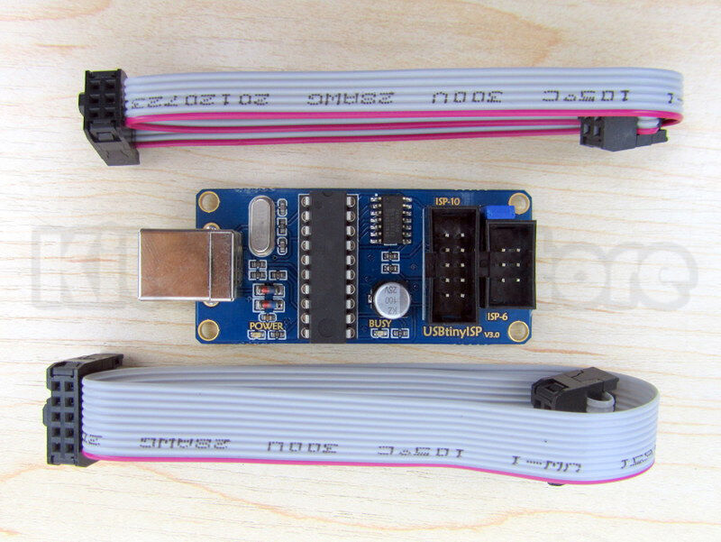
Well to upload the bootloader I needed a programmer. So now I bought what I should have bought in the first place, a usbtinyisp. I got mine off eBay from a US seller for $15 I think. You can also get kits HERE. There's a picture if you're wondering.

I uploaded the bootloader (go HERE for now). I may do a tutorial on this later too. Who knows. Anyway, I upload the bootloader and it appears to go well until I get an error message. It didn't work. However, I notice that the led is blinking on the Arduino. That's odd. Before it was just on all the time. It wouldn't blink even if  I pushed the reset button. I plugged in the USB cable to the Arduino, and its alive again.

I have no idea what the problem was or what fixed it, but it now works again. The moral of this story (for me anyway) is spend the $15 and get an isp. $15 could have saved me many hours. Then again, I learned a lot through this process. I learned a lot about flashing firmware, loading bootloaders, and maintaining patience.

There will be more posts to come now. I hope this helped someone.
Matthew

Tuesday, March 5, 2013

LCD Shield: Calculator

     Today I have for you another project I did with my HobbyKing LCD Shield and my Arduino Mega 2560. I made a calculator! One day I decided that my Texas Instruments calculator was simply not enough. Necessity is the mother of invention so..

     Anyway. I did all I was going to do on my toolbox alarm, so I decided I would start on something new. I thought a calculator would be fun. That's what I did.


What it does now:

  • The user selects add, subtract, multiply, or divide
  • The user inputs the first value
  • The user inputs the second value
  • Answer is calculated and printed to screen

Work for the future:

  • Select number by digit (ie. 1000 = 1-0-0-0. Current model would involve 1000 button pushes)
  • Add push and hold to scroll functionality
  • Add other functions: sine, cosine, power, etc.

      Now I realize that much of the way I did things was a bit impractical. Creating a separate function to add two values is kinda useless. However, this was meant to be a learning exercise. The code that runs the LCD is still mostly the example code found HERE. I did create the menu and such, and that was really the focus of the exercise. I knew I could do it; I wanted to prove that to myself.

Stuff you might want:


     If you are using my code, note that I make no guarantees that it is perfect. If you are just buying the shield, note that I have a review that might interest you. If you have questions, comments, or concerns, post a comment or send me an email. 

     If you choose to undertake this project, I hope you find it interesting. I don't know that I learned anything specific while working on this, but I honed my debugging skills and such. I think this may be the last of my LCD shield projects for a while. I have one more in mind, but that may wait. I've got my ATtiny's waiting on me as well as my IMU that I have been playing with. So much to do, so little time. Anyway. I hope you found this interesting.

Until later,
Matthew

Saturday, March 2, 2013

LCD Shield: Toolbox Alarm


Well I’m back. As you all know, I received my new Arduino and have been playing with it. I must admit having it not tied to a little robot is quite nice, so I haven’t put it on the bot yet. Instead I have been playing with my forgotten LCD shield from HobbyKing. Oh yes you say. I remember that one. Well I have been doing some more stuff with that and decided it’s time to share that with the world. Here it is.
            Today I will talk about the first project I embarked on. It is called the toolbox alarm. This project is a copy of a similar project that is used here at Tech in one of the classes. I just stole it and decided that if I’m going to do this stuff, I should be able to do the less interesting things too. Well I was a bit surprised. I actually found this project slightly fun.


Project Description: Create an alarm system for a toolbox. It should prompt for a 4 digit button sequence and then allow you an amount of time to close the lid. Next, a light sensor will read the light level. If the light level changes (ie. the toolbox is opened) the user will have a certain amount of time to re-enter the passcode before a buzzer sounds.

Well I should tell you that I did not do that. My alarm has no light sensor or buzzer. It just gives you a pat on the back if you get it right and an incorrect if you don’t. Basically, mine is completely useless as opposed to just extremely impractical.

Anyway, I really liked working on this. I got more accustomed making functions and such. The more time you spend looking at code and working on it the better.

I guess that’s about all I have for today. If you want the code I created, get it HERE. It’s free and all that jazz. Go forth and do with it what you wish. If you somehow find a way to make lots of money on it, send me a nice gift or something (I’m pretty confident that won’t happen). The video below is of it running.

            If you need the example code it is HERE. If you need to buy the LCD shield it is HERE. If you want my review of the LCD Shield it is HERE. I can’t think of anything else you’d want. You can find info on the LCD library on your own at arduino.cc.

            I have at least one more LCD shield project I will talk about soon as well as the return of the IMU (That is what I was working on when I fried my last board) and all the sonar sensor stuff. I can’t say which will be next. It depends on my mood. I hope you’ll check back in to see that. If you have any questions about this project, post in the comments or send me an email.

Matthew