Tuesday, March 10, 2015

Fixing Autoscroll in GNU Octave for Windows

Introduction
A quick and dirty post documenting an Octave "fix" for a problem I was having. Running GNU Octave version 3.8.2-5 from MXE installer found HERE on a Windows 7 64 bit PC on 3/10/2015.

The Problem

The output of GNU Octave as installed above has a feature that while I am sure is useful to some, is quite irritating to me. Outputs that are too long to fit on the screen of the terminal are paginated. It will display the values that will fit on the screen and then wait for you to press "f" to see the next page worth's of data. See below. It displays "-- less -- (f)oward, (b)ack, (q)uit" at the end of each page.

While this may be great if you want to see every single value, if you are running long programs where the output is mostly for debugging purposes or similar, this can be irritating. I finally decided to figure out how to change this. Here it is.


A Solution

While I don't claim to understand exactly what is going on above, it is clear that the "pager" being used on my install is "less". I wanted to change it to "more".

1) Check what pager you are using - Type "PAGER()". My guess is it will probably be "less". 

2) View help file on PAGER() - Type "help PAGER". A couple useful websites: Documentation from a German university and Documentation on the Octave Wiki.

3) Change pager to "more" - Type "PAGER("more")

This should make the output look like the picture below. As you can see it scrolled through my entire output just fine. I will note that "PAGER()" now returns "more". Honestly, I don't really know what I changed under the hood, but it worked. Also note that it will reset when you reopen Octave.


That is all I have on this. If anyone has a more detailed explanation of how this works or other ways to fix this "problem" feel free to post in the comments.
-Matthew

Thursday, March 5, 2015

Serial Port Communication with GNU Octave in Windows

This is not so much a finished post as it is a place to record progress. Use any information found on this page at your own risk.

Introduction

I have been using GNU Octave in place of MATLAB on my laptop for a while now. It is free and serves my purposes well. One place MATLAB does have it beat though is in its ability to communicate with outside hardware through a serial port. I recently needed this functionality for Octave. This is how I made it work. My configuration:
  • Windows 7 - 64 bit
  • GNU Octave 3.8.2-5 using MXE installer
  • Instrument Control Package 0.2.1

Walkthrough

Install Octave

If you found this post I will assume you are probably running Windows. There is a convenient unoffical installer for Windows HERE. At the time of this writing I am running 3.8.2-5. Anything greater than 3.8.0 has the nice MATLAB style GUI.

Install Instrument Control Package

The equivalent of MATLAB toolboxes are packages in Octave. You need the instrument-control package to access the serial ports. There are two ways to install it.

1) Install it from Octave forge. Assuming you have an internet connection, open Octave and type in the command window "pkg install -forge instrument-control-0.2.1.tar.gz" Replace the 0.2.1 with the newest version of the package.

2) Download it from HERE. Assuming you did a standard install, move it to the folder "C:/Octave/Octave-3.8.2/src". There you will find all the other packages that were included with the installer. Now open Octave and make that folder your directory. Type in the command window "pkg install instrument-control-0.2.1.tar.gz". Obviously you may need to change the name of the package if you download a newer version.

Both options will take a while. One of my first mistakes was thinking I had crashed my computer. I wasn't sure if it would work on Windows, so when it just sat there for a minute I thought it was hung. Just give it some time. Mine took a couple minutes. 

Load Instrument Control Package

You only have to install the package once, but you need to load it every time you open Octave (you can also set it to auto load. Google it.)

Type "pkg list" to see all your installed packages. If you don't see instrument-control then you need to go back to the last step. Any package with an * by it is loaded.

To load the package type "pkg load instrument-control". Now load the list of packages again to see if it worked.

Use the Package

Now the part you have been waiting for. It is important to note that at the time of this writing the instrument control package is not a drop in replacement for the serial capabilities of MATLAB. Here are some helpful links to illustrate this. It is fairly obvious that the function names are different or missing for Octave.
For my initial test I used an Arduino with a jumper between Rx and Tx. This essentially mirrored anything I sent back to me. To simplify things, go to the device manager and change the serial port number to COM1 through COM8. Over that and additional work is needed. Device Manager > your port > Port Settings > Advanced > COM Port Number.

My Additions
To better serve my needs I added a few files to make the package more MATLAB compatible. Just make sure they are in your path somewhere if you want to use them.

srl_fwrite: Download HERE. Similar to the MATLAB fwrite. The regular srl_write only accepts char and uint8s. I made this function to simplify sending other variable types. Accepts three inputs 
  • Serial Object
  • Data to be sent
  • Data Type - int8, uint8, int16, uint16, int32, uint32, int64, or uint64
srl_fread: Download HERE. Similar to MATLAB fread. Reads serial port and returns data type specified. Takes three inputs.
  • Serial Object
  • Number of values to be returned. (eg for 3 uint64s, enter 3 not 24)
  • Data Type - int8, uint8, int16, uint16, int32, uint32, int64, or uint64

Test Script
Test Script: This script was taken and modified from the wiki linked above. It opens a serial port, sends a couple values and then attempts to read them when the serial device mirrors them back. A "correct" output should look something like this.

Serial: Supported
s1 = 0x444
int8 = 200
intdata =

    0  142    1   44


That is all I have at the moment. I hope this tutorial was useful to someone out there. I plan to do another post on the way I am actually using this capability in the future as a more in depth example. 

-Matthew

Sunday, February 22, 2015

Replikeo Prusa i3 Rework Build - Part 3: Wiring and Software Setup

Part 3 will cover my wiring of the Replikeo Prusa i3 Rework (mostly following the wiki page). Then I will cover my setup of the Repetier Firmware. I'll save first prints for Part 4. If you are interested in the unboxing and assembly see Part 1 and Part 2 respectively.

Wiring

"Completed" Wiring

As the wiki page already has a very complete set of instructions on wiring, I will refrain from giving a step-by-step description of the procedure. I will instead clarify a few points that caused me a bit of confusion or could cause confusion.

1) The Arduino does indeed mount in the holes shown on the wiki page. The USB port points down. I initially could not manage to get the holes lined up, but they eventually cooperated.

2) The endstops as wired in the picture are connected to the min endstop pin. That doesn't really matter right now, but you will need to know that when you go to setup the firmware.

3) On the power supply L=Line, N=Neutral, and G= Ground. I used a multimeter to find out which wire goes to which pin. If you live in Tennessee you should have about 120 VAC across the line and neutral. Be sure you change the switch on the power supply to 110V mode.

4) When wiring the motors you can plug both Z motors into the ramps board. There are (quite conveniently) two headers there. You don't have to have an external combining pcb as shown in the picture on the wiki.

5) I used the fan that came with the Replikeo kit as an extruder cooling fan, not a "Print Fan". As such, I did not connect it to D9. This required that I crimp on an old servo connector I had to attach it to the extruder fan pins. These are just a 12V breakout. Whenever you plug your printer in, it is going to come on.

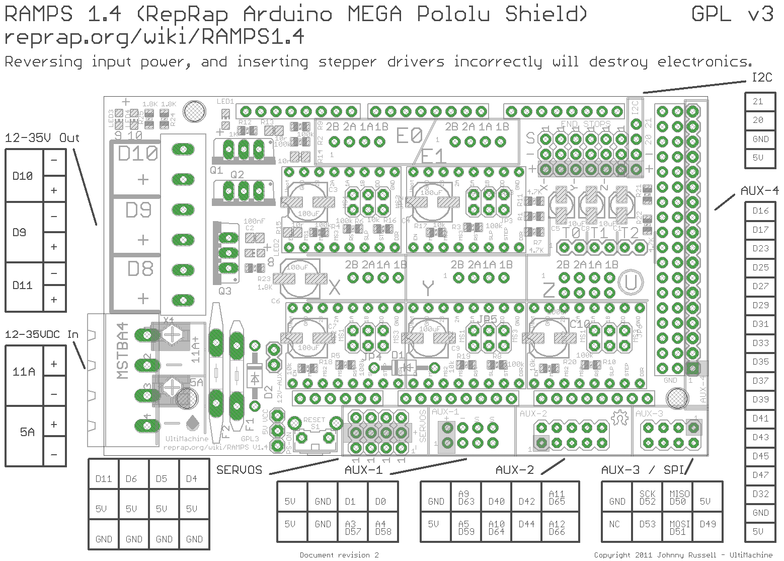
Ramps 1.4 Pinout

 Software

I am using the Repetier Firmware with Repetier Host and Slic3r. Repetier has a very convenient web setup tool. It really wasn't all that difficult and was pretty helpful in figuring out how things worked, but if you are having problems and want to try the firmware I am using download mine HERE. Just upload the configuration.h file and see what's going on. One thing to remember, some of the settings may be getting set in EEPROM. This means you will need to update them from Repetier Host. It's under the Config tab. 

In Repetier Host, be sure to input all the correct Printer Settings. For instance I have a max x endstop and the other two are mins. And my bed is actually 190x170. If you follow the installation instructions on Repetier's website you should be fine.

In Slic3r for the ABS that was included with the kit a lot of the default settings work fairly well. For the filament settings my diameter measured to be about 1.73mm and I print at 230 for the first layer and 215 for the rest. Bed is at 100. I also had some success starting the bed at 100 then dropping it to 85. I have not been able to calibrate the thermistor yet, so I can't be verify that those are the actual temperatures. But those settings work for me.

Now the fun part begins, You get to go play and test things. I doubt very many people will read this and use it as a guide to assembling their printers. However, if you are trying to decide if this is the printer for you, I can confirm that the wiring and software is equally simple. A few hours and I had it working.

That's all for part 3. In part 4 I will show some pictures of my "completed" printer and the modifications I made. Some of them are good. Some of them still require work.

-Matthew