Showing posts with label Mega 2560. Show all posts

Saturday, November 26, 2016

Arduino Interrupt Stepper Driver - CTC Mode

Introduction to the Problem

This tutorial will show how to drive a Pololu style stepper (A4988) driver using a timer interrupt. This method is non blocking, efficient, and as far as I know is pretty much what most 3D printer firmwares use.

The idea is this. A pololu style stepper driver (the kind that plugs into the RAMPS board) only requires two inputs from the Arduino. One is a direction pin. The other is a pulse train. One rising edge equals one step (or micro step, depending on how the set pins are wired). Most people when they first get going with steppers probably do one of two things. 1) They use some library that does all this for them (I don't know if one exists, but maybe it does) or 2) They just throw a digitalWrite in the loop() and pulse it that way. The problem with that is that it is dependent on the speed with which the loop runs. Enter Timer Interrupts

Interrupts - Conceptually

The timer interrupt is a low level feature of the ATmega family. It is not something that is provided by Arduino, and in fact functions such as millis() and delay() are based on them. I have always been a bit surprised that Arduino does not break timer interrupts out a little. They are really pretty easy to use but are very powerful. I am not going to go into great detail on the specifics of timer interrupts because there are other sources out there. The best of which is the ATmega datasheet.

The idea is this - the ATmega CPU is sitting there executing your code, pulling commands off of the stack. It does this in the same order each time. On another part of the chip there is this thing called a timer. It is counting up from 0 to some value over and over again incrementing at a set frequency. When it reaches the target value it sets a flag and goes back to 0. When that flag is set, the ATmega chip sees it and says, "it is time to execute a special piece of code. Drop everything and do it." What ever it was doing before goes back on the stack and what you put in the "interrupt service routine (ISR)" gets executed. Then it goes back to its normal business. We want to put our "pulse stepper driver" code in the ISR.

There are a couple of dangers with this, but I will just leave you with this. Keep the ISR short. Don't do any serial prints or heavy computations (floating point math) in there. Calculate those ahead of time and pull them in as compile time constants ideally.

Solving the Problem

Now I actually came up with 3 ways of solving this problem
  1. Using a fixed rate Timer Interrupt and only pulsing on some of the ISRs
  2. Using CTC mode and pulsing inside the ISR
  3. Using a special PWM mode 
This tutorial covers method 2. It uses Timer5 in Clear Timer on Compare (CTC) Mode. This allows you to call an interrupt at whatever frequency you want. If you're familiar with timer interrupts  the picture below might help. Again, I will not take the time to go into that much detail on that in this post. For now, I will point you to the ATMega datasheet which covers all of this stuff and THIS post by maxembedded.
CTC Mode - From ATMega Datasheet

Another important point is that I use direct port manipulation in the interrupt. I will not cover that here, but there are numerous examples online of how that works in addition to the ATMega datasheet. HERE is one example. I use direct port manipulation because it is much faster. As stated above, the ISR should execute as quickly as possible.

The Practical Stuff

Copy the code below. Wire it according to pins set in the code. Change the pulses per second calculation based on your setup (change it in the ISR Location calculation too). Set targSpeed in mm/s. Then set the Z_DIR_PIN and DirFlag based on the direction you want to drive. Test your code.

I hope this is helpful to someone. If it is, please let me know in the comments. If anyone that reads this has any insight into libraries available or other methods, comment those too. Good luck!

-Matthew


/*
 * Drives stepper using a pololu stepper driver and timer interrupts
 * 
 * This example uses pinouts associated with RAMPS 1.4 z-axis
 * 
 * Last edited by Matthew 11/14/2016 Arduino 1.6.7
 *                projectsfromtech.blogspot.com
 * TRCCR1A/B               
 * COM1A = 0b00 - disconnect OCR
 * WGM1 = 0b0100 - Fast PWM with the top value at compare match
 * CS1  = 0b001 - no prescaling               
 * ICNC1 = ICES = 0b0 - doesn't apply
 * 
 * */

const byte Z_STEP_PIN    =     46;
const byte Z_DIR_PIN     =     48;
const byte Z_ENABLE_PIN  =     62;  //62

//Interrupt Variables
volatile uint16_t PulseOnISRNum = 0;
volatile uint16_t isrSincePulse = 0;

//============================================================================
void setup() {
  Serial.begin(115200);

  pinMode(Z_STEP_PIN, OUTPUT);
  pinMode(Z_ENABLE_PIN,OUTPUT);
  pinMode(Z_DIR_PIN, OUTPUT);

  //setup Timer1
  TCCR5A = 0b00000000;
  TCCR5B = 0b00001001;
  TIMSK5 |= 0b00000010;       //set for output compare interrupt
  sei();                      //enables interrups. Use cli() to turn them off
}

float targSpeed = 2.5;       // mm/s
float PPS = 0;               // Pulses Per Second
int8_t DirFlag = 1;          // Direction flag. Set this to keep track of location
int32_t Location = 0;        // nanometers (m*10^-9) scaled by 10^-6 to avoid floating point math in interrupt

long clk = micros();


//============================================================================
void loop() {
  //Set Direction
  digitalWrite(Z_DIR_PIN, LOW);     // Low is forward   (based on setup)
  DirFlag = 1;
//  digitalWrite(Z_DIR_PIN,HIGH);       // High is backward (based on setup)
//  DirFlag = -1;
  digitalWrite(Z_ENABLE_PIN , LOW);   // Active Low

  // Set Speed - these calculation are based on your harware setup
  //           - Mine are for 1/16 microstepping and an m5 threaded rod driving the stage
  //------------------------
  for(float ind = 0 ; ind <3.0 ; ind = ind+0.0005)
  {
  targSpeed = ind;            // mm/s
  PPS = targSpeed * 4000;     //Pulses/s
  OCR5A = 16000000/PPS - 1;   //equation from pg 146 in datasheet- removed factor of 2 b/c I am manually pulsing in an interrupt every time
  Serial.print("Speed (mm/s): ");
  Serial.print(targSpeed);
  Serial.print("  Loop Time (ms): ");
  Serial.print(micros()-clk);
  Serial.print("  Location (mm): ");
  Serial.println(Location/1000000.);
  clk=micros();
  // Input other code here! Stepper driver will run even if this code is blocking!


}}

//================================================================================


ISR(TIMER5_COMPA_vect) {
//    digitalWrite(46, HIGH);       // Driver only looks for rising edge
//    digitalWrite(46, LOW);        //  DigitalWrite executes in 16 us  
    //Generate Rising Edge
    PORTL =  PORTL |= 0b00001000;   //Direct Port manipulation executes in 450 ns  => 16x faster!
    PORTL =  PORTL &= 0b11110111;
    Location = Location + 250 * DirFlag ;  //Updates Location (based on 4000 Pulses/mm)
}
    

Wednesday, November 20, 2013

Arduino PPM Decoder: Decoding an RC Receiver with an Arduino

In this post I will detail how to decode the PPM signals from an RC receiver using an Arduino. Specifically, I will decode the signals from a 6 channel OrangeRx receiver using an Arduino Mega 2560 r3 and my custom PPM encoder board that I describe HERE.

As most interested people know, the only good way to do this is with interrupts. While pulseIn will work for a few channels, more than 2 or 3 will bog it down too much to do anything useful.

Step 1
Access PPM Stream. THIS site describes what I mean by that. In short, we want to combine the single signal from the six individual pins into six signals on an individual pin. This allows us to decode all 6 channels with one hardware interrupt. That's something any Arduino can handle.

Like I mentioned above, you will need my PPM Encoder to do that (there are other options that I discuss in that post as well). Luckily, it is fairly cheap and easy to make. You may ask, "Why can't I just wire all the pins together?" In short, it doesn't work. I tried. This is because when one pin is high, five are low. Again, more details are in my other post.

6 Channel PPM Stream

Step 2
Decode the PPM Stream. As you can see in the picture above, the PPM stream consists of six spikes that we need to decode. Now, there are many descriptions online about how to decode these signals using interrupts, but I wanted a hardware independent approach. I didn't want to have to worry about my timers not working when this code is running or anything like that. For that reason, I wrote some fairly simple code that runs right in the Arduino sketch (vs tucked away in a library). I just set a hardware interrupt that triggers from a rising signal and subtract the times between each. (Read more on interrupts HERE). This of course causes a problem for channel 6 which doesn't have a signal coming after it. For this reason we have to do a few other things when we get to channel six.

HERE is my code. Look at it for yourself. It reads the values from the RC receiver, scales them to 1-100 and then prints them to the Serial Monitor. I'm not entirely happy with the way that I handled channel 6 at this point, but it works fine. I initially tried getting its value inside Spike(), but the micros() function does weird things inside it. I may revisit my approach someday, but it works for now. Though I wouldn't put anything life threatening on channel 6 (or any of the channels for that matter..). Below is an example output.


There you have it. A simple Arduino PPM signal decoder. Now you can get inputs from virtually any RC receiver and use them in your projects, library free. Hopefully you found this useful. As always, if you have any problems comment below and I'll see if I can help. If you had success, great! I'd love to hear about that as well. If you like this post, check out some of my others by clicking on a label that interests you.

Best of luck,
Matthew

Saturday, November 16, 2013

iRobot Create - Arduino interface cable

This post details the construction of a custom Arduino interface shield and cable for the iRobot Create. See my tutorial series on the iRobot Create. This cable allows the user to easily and cleanly interface with the Create and communicate with it via the Arduino Mega2560's Serial1 port.

Parts List:

Assembly is fairly self explanatory when you see the pictures. Here are a few useful charts.

Arduino Mega PinCreate Cargo Bay Pin
TX1 (pin 18)RXD (pin 1)
RX1 (pin 19)TXD (pin 2)
GNDGND (pin 14)

The chart above shows the connections that must be made. Note that Serial0 on the Arduino cannot be used without additional external hardware.


Cargo Bay Pinout.JPGArduinoMega pinout.png
First things first, assemble the protoshield as per THESE instructions.

Next, solder the ribbon cable to the DB25 connector. I chose to do it in such a way that the pins would be mirrored on both end. Note the way the ribbon cable connectors work, every other wire is connected to the top row. Really, the only important thing is that you include pins 1, 2 and a ground. Crimp the ribbon cable connector on.

Now you need to solder on some male headers to the protoshield. This is where the ribbon cable will connect.

Connect the male header that corresponds to the ground to the ground pin on the Arduino. Use the colored wire to make a jumper that will go from the RXD and TXD pins to the Arduino TX1 and RX1 pins respectively (in the picture below, it is the black and white wire in the bottom center).

Note that Serial1(TX1/RX1) must be used on the Arduino Mega (the Uno will not work without external hardware). The serial port output TXD from the Roomba/Create is too weak to drive the RX serial port (Serial0) input of an Arduino properly. This is because of the USB-Serial converter on the Arduino: it also tries to drive the RX serial port input via a pullup resistor, but the Roomba does not have enough drive to pull the RX down below about 2.5 volts, which is insufficient to be reliably detected as a TTL serial input of 0. Furthermore, using Serial1 still allows for the use of the Arduino Serial Monitor for debugging purposes. Also note that Serial2 or Serial3 could be used if selected in software.

Test your board and see if it works!

I hope this post was somewhat useful. It isn't so much of a how to as it is a description of what I did. There are many ways to do it. Really, the only important thing is that you connect TXD to RX1, RXD to TX1, and GND to GND. When you do that, you'll be ready to head back to my tutorial series!

Matthew

iRobot Create: Arduino Control

Introduction

This is the fourth section of the iRobot Create tutorial. If you have not completed the first sections, I would recommend that you go back and do so by following the links below.

Sections

Reference Documents

These documents should be referenced for details on interfacing with the Create
  • iRobot Create Open Interface Manual (OIM)- This manual provides detailed information on the serial interface with the Create. It details the implementation of the opcode system used to control the various systems as well as the necessary measures that must be taken to receive sensor data from the Create. Information regarding sensor packet size, connector pinouts, and command details can be found here.
  • Roomba Class Reference Guide (CRG)- This document provides support for the Arduino "Roomba" library. Here details can be found regarding the functions included in that library.
  • iRobot Create User Manual - This manual provides an introduction to the basic functions of the Create and an overview of the basic onboard functionality

Necessary Hardware

Necessary Software


Arduino Control

Arduino control can be implemented using the Roomba library. This library handles all the background serial commands allowing the user to program the Create's functions using the Arduino IDE. If the Roomba library is not installed download it HERE. Unzip and install the library then restart the Arduino IDE (See How to Install a Library).

Arduino Basics

This tutorial assumes basic knowledge of the Arduino IDE. If instructions are unclear or problems arise concerning the Arduino system, refer to THIS page and my previous posts (the ones labeled Arduino).


Wiring

Connecting the Arduino Mega to the Create is simple. In general, connections should be made according to the chart below. See my post, iRobot Create - Arduino interface cable.
Note that Serial1(TX1/RX1) should be used on the Arduino Mega. The serial port output TXD from the Roomba/Create is too weak to drive the RX serial port (Serial0) input of an Arduino properly. This is because of the USB-Serial converter on the Arduino: it also tries to drive the RX serial port input via a pullup resistor, but the Roomba does not have enough drive to pull the RX down below about 2.5 volts, which is insufficient to be reliably detected as a TTL serial input of 0. Furthermore, using Serial1 still allows for the use of the Arduino Serial Monitor for debugging purposes. Also note that Serial2 or Serial3 could be used if selected in software.
Arduino Mega PinCreate Cargo Bay Pin
TX1 (pin 18)RXD (pin 1)
RX1 (pin 19)TXD (pin 2)
GNDGND (pin 14)
Cargo Bay Pinout.JPG
ArduinoMega pinout.png

In this tutorial, connections will be simplified using a custom interface shield and ribbon cable. Connect the Arduino as shown below. See THIS post for details on the custom interface shield and cable.
IRobot Create Arduino Wiring 1.jpgIRobot Create Arduino Wiring 2.JPG
Note:
  • The direction of the ribbon cable is important. It must be connected as shown.
  • The connection of the TX/RX cable is important. Connect it exactly as shown.
    • White: TX1 pin 18
    • Black: RX1 pin 19
  • When using the cargo bay connector, ensure that the mini-DIN connector (the one used with the Create serial cable) is unplugged.

The recommended input voltage for an Arduino is 7-12V, center positive. Verify battery voltage before connecting. 


Checking Connections: TestSuite

This example is included in the Roomba library (see "Necessary Software"). It allows for a quick assessment of Arduino-Create communication.
1) Open TestSuite.pde - In the Arduino IDE: File > Examples > Roomba > TestSuite
2) Connect the USB cable to the Arduino. Install the driver if not already done (How to Install Arduino Drivers)
3) Upload Program
  • Tools > Board > Arduino Mega 2560
  • Tools > Serial Port > [COM port]
  • File > Upload 
4) Open Serial Monitor - Set baud to 9600
5) Restart Arduino Mega by pressing restart button

A message indicating 0 errors should be displayed in the Serial Monitor and the Create should play an audible melody. If errors are reported, check the items listed below. Proceeding to other examples will be futile until these errors are eliminated.
  • TX/RX cable: White -> pin 18 , Black -> pin 19
  • Orientation of ribbon cable
  • Serial monitor baud rate
  • Arduino Driver Installed
  • Correct COM port selected

Controlling Drive Output

This example shows the basics of controlling the Create's movements. There are 2 basic functions that can be used to control the Create's drive motors. The Roomba library provides support for both. Details regarding usage of the 2 functions can be found in the Roomba Class Reference Guide. Information on maximums, minimums, and special cases can be found in the Open Interface Manual. 
  • drive(int16_t velocity, int16_t radius) - Velocity is in mm/s. Radius is in mm. Special values can be found in the CRG.
  • driveDirect(int16_t leftVelocity, int16_t rightVelocity) - Velocity is in mm/s.

1) Turn Create to OFF.
2) Open Roomba_Drive_Test.ino - In the Arduino IDE: File > Examples > Roomba > TTU Examples > Roomba_Drive_Test.ino or copy sketch from link at the bottom of the section.
3) Upload it to the Arduino Mega.
WARNING: If the Create is on, the sketch will start as soon as the upload is complete. Before uploading, turn the Create off. It is important to note that the Create may be ON even if the power LED is off. The power LED turns off when the Create is put in safe or full mode as well. Cycling power until the power LED is lit and then goes off will ensure that the Create is truly OFF. Regardless, it is a good practice to ensure that adequate space is available in case of accidental movement.
4) Disconnect USB and connect Arduino external power.
5) Place Create on large, flat surface (ie. the floor)
6) Power up the Create.
7) Restart Arduino.
The Create should cycle through a series of movements using the two methods of control as defined below. 
  • driveDirect
    • Drive straight
    • Spin CounterClockwise
    • Spin Clockwise
    • Stop
  • drive
    • Turn Left
    • Turn Right
    • Drive Straight
    • Spin Clockwise
    • Spin CounterClockwise
    • Stop


Reading Sensor Data

Sensor data can be read in two different ways. While both methods are described in the OIM, this example will only cover the getSensors() approach. The Create automatically updates its sensor data every 15ms. The user can choose often to read the values of those readings. While calling getSensors more frequently will cause no harm, the values read in that period will be redundant.
To read a sensor, the following information is needed
  • Sensor packet ID - the number associated with the sensor value the user is trying to read. Packets 0-6 are associated with groups of sensor values. Packet 6 is associated with all sensor values available 
  • Size of sensor packet (in bytes) - the number of bytes returned when the user calls a sensor packet ID 
  • Variable type returned - the way the bytes received must be interpreted. 
Example 1: Packet 7 returns one byte. However, it must be interpreted as individual bits. A value of 3 means that bytes 0 and 1 are 1s and therefore the Left and Right Bumpers are triggered.
Example 2: Packet 28 returns 2 bytes. They must be interpreted as one unsigned integer value. As in the "Drive Forward 20cm" example, a value of 1 and 44 would mean that the Left Cliff Sensor is reading 300.
All of this information can be found in the Open Interface Manual beginning on pg. 17. 
Useful Arduino functions for interpreting sensor values
  • bitRead - Reads an individual bit in a byte
  • Bitshift - Shifts the bits in a variable in either direction. Useful for high_byte, low_byte composition
  • BitShiftCombine - Function included in the example (defined at the bottom). Uses Bitshift to combine to bytes into a 16 bit int. Note that the int may be signed or unsigned depending on the receiving variable type. 

getSensors(uint8_t packetID, uint8_t* destination, uint8_t length)
  • packetID - number of packet to read
  • destination - an array with at at least "length" entries. Note that arrays are 0-indexed. ie, the first value in an array of 52 entries is array[0]. The last entry is array[51].
  • length - number of bytes associated with packetID being used.

Process for running sketch:
1) Open Full_Sensor_Test.ino - In the Arduino IDE: File > Examples > Roomba > TTU Examples > Full_Sensor_Test
2) Upload sketch to Arduino Mega
3) Open Arduino Serial Monitor - Set baud to 57600
4) Power ON Create
5) Restart the Arduino
Data from sensor packet 6 (all sensor data) should be displayed in the Serial Monitor. For more information regarding the nature of the sensor data, see the Open Interface Manual.


Basic Object Avoidance

This example demonstrates the use of the Create's sensors to navigate around obstacles. When executed, the Create should drive forward. When it bumps into an object, it should back up and turn away from the object. Sensor data is read using getSensors and motor control is implemented using driveDirect.


1) Turn Create to OFF.
2) Open Basic_Object_Avoidance.ino - In the Arduino IDE: File > Examples > Roomba > TTU Examples > Basic_Object_Avoidance
3) Upload sketch to the Arduino Mega.
WARNING: If the Create is on, the sketch will start as soon as the upload is complete. Before uploading, turn the Create off. It is a good practice to ensure that adequate space is available in case of accidental movement.
4) Disconnect USB and connect Arduino external power.
5) Place Create on large, flat surface (ie. the floor).
6) Power up the Create.
7) Restart Arduino. 

Friday, August 23, 2013

Arduino Mega 2560 r3 Doesn't Show Up in Tools Menu

Recently, I have had problems with my Arduino Mega 2560. Serial communications would drop in and out. It would not show up in the Arduino IDE Tools menu. Annoying stuff. Looking around on the internet, it appears that this is a fairly common problem, so I thought I would post what I know about a solution.

If your Arduino Mega doesn't show up in the Tools menu, the first thing you need to do is open the device manager (on Windows. If you have a Mac then you should mail it to me and go by a Windows machine). From the device manager we can further diagnose the problem.

1) Your Arduino shows up nicely under the COM ports tab. This is quite possibly the most frustrating problem, and as far as I can tell no one really knows why this happens. Here are some things that I did that sometimes worked. Try a combination of them.

  • Disconnect and reconnect the Arduino
  • Re-install the Arduino Drivers 
  • Re-install the Arduino Drivers deleting them when you remove them. ( I believe there was an update to the Mega driver somewhere around Arduino 1.0.2)
  • Restart the Arduino IDE
  • Turn off  your WiFi (My computer has bluetooth built into the network card. Bluetooth COM ports can cause problems sometimes. Turning off networking solves this).
  • Reinstall the ATmega16U2 firmware. (Instructions HERE)
  •  Get frustrated and go work in your garden
2) Your Arduino shows up as an unknown device. Install the drivers. I can't think of any other reason this would happen.

3) Your Arduino shows up as an unknown Atmel device. The Arduino Mega 2560 r3 has a ATmega16U2 that acts as a USB to serial chip. If you are getting an unknown Atmel device it means that this chip has been put into DFU mode. This is not the end of the world. Usually you can just disconnect and reconnect the Arduino, and it will go back into it's normal mode. If that doesn't work see my previous post on this subject.

4) Your Arduino shows up as an Atmel device called ATmega16U2. Well this means the same thing as above. It is in DFU mode except you have already loaded the Flip programmer driver. You have already started the process, so go HERE and finish.

5) Your Arduino does not show up in the device manager at all. This is a pretty major problem, but I found this one almost freeing. You can try various things. If you have an external ISP you may be able to reflash the ATmega16U2 and save it. I believe there are some instructions for doing so in a README file in the Arduino firmware folder. You should try a different USB cable obviously. Wiggle the wires. Blow out the connection with air. However... the chip may be fried. What does this mean?

If it is just the ATmega16U2 that is trashed then you can still use your Arduino Mega! Now you will just need an external programmer to program it. I recommend having one of these anyway. A USBtinyISP is maybe $15. I have used it extensively with ATtinys and even detail how to use it with a Mega HERE.

But now you want to get that nice Serial Monitor for debugging. Well that again will require extra hardware. You will need an external USB to UART cable. I talk about them HERE. Mine was $4. It's a worthwhile purchase anyway.

If none of those things tickle your fancy, buy another one. Places like HobbyKing sell them for less than $20 (HERE). Look for "Arduino compatible" boards. No one likes a counterfeit.

One last problem that I want to throw in here. The Tools menu freezes or crashes. There are mentions of this HERE. Like I said above, turn off your WiFi. You can also look and see if there are any Bluetooth scanning programs running. I haven't found any quick way of doing this besides looking through the system processes and closing stuff that sounds suspicious. Believe me, I know how annoying this problem is, but that's life. Arduino 1.5 does seem to do a bit better.

If you have other ideas, suggestions, or words of encouragement comment, and let the world know. There may be other things out there you can try.I hope this brings you success. Good Luck!
-Matthew


Wednesday, August 7, 2013

Serial Sonar Sensor: ATtiny85, HC-SR04, and Arduino SoftwareSerial

In this post I will detail how I used an ATtiny85 as a controller for an HC-SR04 sonar module (Ping sensor). The controller reads the inputs from up to 3 HC-SR04 modules and transmits the readings to an Arduino Mega via serial communication. This allows the Arduino Mega to pick up the readings whenever it is convenient rather than having to worry about complex timings. Let's get started


First things first, we need to run the NewPing library on an ATtiny85/45/25. Until version 1.6 is released you will need to modify the library to do this. However, this removes some of the functions you might want to use on other boards. For this reason, I created the TinyNewPing Library. In it, I removed the parts that cause the errors on an ATtiny and gave it a new name so you can distinguish between the two. All the function names remain the same. If you still need more details check out THIS prior post.

Next we need the SoftwareSerial Library on the ATtiny. Luckily, this comes with the IDE and I already did a post on it. Funny how that works.

For a first attempt, try a single HC-SR04 sonar sensor. This simplifies the code a bit. Load THIS code on the ATtiny (sensor side) and THIS code on the Arduino Mega. Note the code uses both Serial and Serial1 (thus the Arduino Mega).

To wire it up, connect the echo and trigger pin together and then connect them to pin 0. Wire in 5V and ground to both the ATtiny and the HC-SR04. Then connect pin 4 (Software Tx) on the ATtiny to pin 19 (Rx1) on the Mega. Finally, plug the Mega into the computer via USB.

Now if this is working ok, we can move on to 3 sensors. For that, we need to load THIS code onto the ATtiny and THIS code onto the Arduino Mega. The ATtiny takes the readings and sends them to the Mega. The Mega updates it's variables and sends them to the Serial Monitor for us to see.

Wiring it is cumbersome but simple. Regrettably, I did not take a picture when I did it, but just do what you did before an extra two times. Note again that we are using the same pin for trigger and echo, so they need to be wired together. Then wire up power and grounds. Finally connect the ATtiny to the Mega and the Mega to the computer.

Now open the Serial Monitor and watch the numbers scroll by.

Potential problems: If the ATtiny gets out of sync with the Mega (it will), an occasional bad value will come up. I couldn't come up with a quick fix for this. If that is a problem, maybe you could take the median of a few readings. They are coming in pretty quickly. The plan is to make an I2C version of this soon, but I make no promises on a deadline. One last download, get the entire package of sketches used in this post in a zip file HERE.

A few quick notes before we go.

  • Why not I2C? That's next (Done! Check it out HERE). Serial is easier because it doesn't require a 3rd party library to work on the ATtiny line. 
  • Why only 3 sensors? Short answer, ease of use. You might be able to get 4 or even 5 out of an ATtiny45 if you're persistant. I don't have that many sensors nor that much patience. You have 5 regular IO pins plus the reset pin (which can be used as an IO). You might be able to use the serial Rx pin as an input as well. 
  • Why not just buy a I2C ping sensor and be done with it? Well this reduces the number of wires going to the Arduino Mega. It also gives you more options and increases the number of micro controllers on board your robot (cool factor). Other than that, it's cheap. With HobbyKing or Ebay, this project could be done for less than the price of one I2C sonar sensors.
Hopefully someone will find this useful. If anything goes great, please comment! If anything goes wrong, contact your local internet service provider. I blame them (That's a joke. You can comment below as well).

-Matthew

Tuesday, June 11, 2013

Multiple Simultaneous Serial Communications

As I mentioned in an earlier post I have an Arduino Mega with a broken USB to serial chip. With that in mind, I thought it would be useful to have an external USB to UART cable. Mine was $4 on Ebay. When it arrived I set to work ringing it out to make sure it worked. Here are the results.

Because my "broken" Arduino is still on my robot, I just used my working one. It is a supposedly identical Arduino Mega 2560 R3. As I played with this I realized that I could communicate with 2 ports simultaneously now (or 3 if I broke out my Bluetooth again). Why is this useful? It's not at the moment. This is really pretty simple, so this will be a short post.

Step One: Wire it up. With my cable it is as follows.

  • Black: Ground
  • Green: Tx (using Tx1 pin 18)
  • White: Rx (using Rx1 pin 19)
  • Red: 5v (this is optional if you have an external power supply).
It is worth noting that my cable does not allow for auto reset. This means that it is pretty difficult to load new programs to the Arduino with the default bootloader. 

Step Two: Load program on Arduino. This very simple. HERE is my example. When you're done, leave the USB plugged in.

Step Three: Open the Serial Monitors and watch for the messages. You will either need to use another program like Tera Term as mentioned in THIS post, or you can open two windows of the Arduino IDE.

That's all there is to it. Now you can communicate with the computer via two serial ports "simultaneously." If you need more information on Serial communications check out THIS post. I also have a post on I2C communication as well as Bluetooth.

-Matthew

Friday, June 7, 2013

Arduino Bluetooth with a HC-06 and JY-MCU

With the arrival of my Bluetooth module I decided to give wireless communication another try. I'm glad I did. Setting up my Bluetooth module for wireless communication took less than an hour. While I have not explored it very in depth yet, I can see myself getting some use from this module. It becomes a generic wireless COM port. I have even read about uploading sketches via Bluetooth if you use a custom bootloader. I will probably never delve into that, but let's get started with the basics.

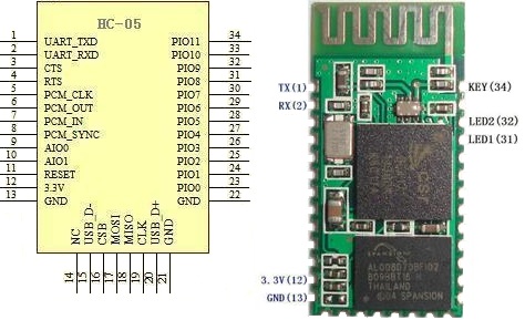
When I first ordered my Bluetooth module, I got a "Bluetooth Serial Transceiver Module Base Board with Enable function For Arduino" from Ebay. I payed a few dollars for it only to realize when I got it that the board was merely a breakout (called a JY-MCU) for another board. Another purchase later, and I had all the things I needed to get going. I got an HC-06 (aka "New Mini 3.3V wireless Bluetooth Transceiver Slave Module Serial Port 30ft TTL"). There is also an HC-05 which apparently is very similar (it seems to share the same pinout).


HC-05 pinout
First things first, I soldered my HC-05 onto the JY-MCU. These can be purchased already soldered for less than $10, but the soldering was good practice. I held the module in place with double sided tape and a piece of tape around the end while I soldered it. The contacts aren't too small, but you will need a decent soldering iron with a small tip.
My impressive soldering


Next I wired it up. This is the point where I began calling on the collective knowledge of the internet. Follow THIS Instructable. With a few changes, it is what I did. For the voltage divider I used a 2.2k Ohm and a 1k Ohm + 100 Ohm resistor. It worked fine. I checked it with the volt meter and it came out to about 3.1v. HERE is the voltage divider calculator I used. Be sure you use that on the Bluetooth Rx/ Arduino Tx side or else you could fry your Bluetooth module. The ATmega 2560 will accept 3.3v so the Arduino Rx is fine by itself (sort of. I wouldn't put this on anything too important, but worst you will get false data). Someday I'll get a real logic level converter. For convenience, I used the Serial1 pins on my Arduino Mega 2560.

Now you need to load a test sketch onto your Arduino. I used the one on the Instructable (with Serial changed to Serial1). To do this you will probably need to unplug the Arduino Rx pin. Should we have loaded the program before wiring like the Instructable said? Probably. Oh well. Take this opportunity to double check all wiring and ring them out with a volt meter.

Now we need to connect the HC-06 Bluetooth module to the computer. I am running Windows 7, and this took about 3 minutes. The steps are on the Instructable, but I would feel bad if I didn't post all the screenshots that I took. Power up your Bluetooth module and follow the steps below.

1) Find the Bluetooth Icon in the bottom right hand portion of the screen. Right Click and Select "Add a Device." My device was called linvor. Whatever floats their Chinese boat. The password for mine was 1234. If that doesn't work, try 0000.


2) Go to Devices and Printers and see if it appears. Wait for Windows to install all necessary drivers. note what COM port it is using. Mine uses two apparently.. Oh well. Not worth the energy to worry about it.


3) Download a terminal emulator program. "Can't I just use the Serial Monitor???" No. Only one device can use a serial port at a time. That is why the Serial Monitor shuts down when you upload a sketch. "Then what should I use???" Well I used Tera Term like the Instructable said because it was the least confusing to a simple mind like me. PuTTy and RealTerm are probably more popular choices. I haven't explored them. I'll assume you use Tera Term.

4) Connect to the module in Tera Term. This is super simple. Select the right COM port.


5) Bask in the beauty of the numbers streaming by. 


This took all of an hour for me. I was astonished at how painless it was, especially compared to my struggles with the nRF24L01+. I am not sure what I will do with it now (I have some ideas). I hope you all have the same success I did. If you need the sample sketches for some reason, they are HERE.

Best of luck,
-Matthew


Tuesday, June 4, 2013

Arduino RTC: TinyRTC v1 with Arduino Mega 2560

This post is slightly out of sync with my previous ones. I was digging around in my parts box and found my real time clock (RTC) module, a TinyRTC v1. I then realized that I had not posted any of my findings when I used it. Well I had a few minutes today, so I decided to dust off the RTC and see if it was still working.

A real time clock is something many new hobbyist might take for granted. Living in a world of computers with integrated RTCs and internet connections, it's easy to forget just what it takes to keep track of the time. While any Arduino can give you the time since it's last restart (or pretty close to it anyway). To keep track of the time displayed on your cuckoo clock you will need some external hardware and a continuous power supply. Various people have come up with  good combinations of said hardware, and all you need to do is buy a RTC module.

The module I will be using is a Tiny RTC v1 module. They are commonly found on Ebay called "Real Time Clock DS1307 I2C AT24C32" or similar. Communication is done over an I2C interface. It has a battery on-board that can supposedly last for several years.

I didn't really remember how I set up the RTC, so I started digging around. I found 2 sketches that I picked up from somewhere. I believe the Ebay seller posted them. I tried them out, and they do work as expected. SetRTC sets the RTC with a time you hardcode into the sketch. GetRTC simply displays the time given from the RTC. Both sketches require the Wire library and the I2C address. To find the I2C address, use THIS I2C scanner.

First wire it up. Connect SCL and SDA to the appropriate pins (21 and 20 on the Arduino Mega 2560). Connect Vcc to 5v and GND to GND. Ignore the rest of the pins. To the right is a diagram of the connections for an Uno if you are confused. Next set the time in the function and upload SetRTC to your Arduino. Then hit the reset button at the moment you want to set the clock.

Now we can upload the GetRTC. Open the Serial Monitor and watch the seconds tick by. An interesting note, if you unplug the GND and reattach it, the time gets corrupted, and you will have to reset the time.

Now, while this method works, I would be remiss if did not mention the Time library. It has many other functions that may be useful depending on your situation. I have not explored them, but I assume it works well. To set the time using the library you will need to download Processing. By using a Processing sketch, you can sync the clock's time to that of your computer.

That's all for today. Go forth and make data loggers, binary clocks, and other exciting projects.
-Matthew

Thursday, May 30, 2013

Stepper Motors and Arduino: 28BYJ-48 with ULN2003

Today I will be exploring the world of stepper motors. I recently purchased a 28BYJ-48 stepper motor with a ULN2003 controller. They are available from a host of vendors for a few dollars and seem to be pretty popular in the Arduino community.

Getting started, there are several links you might find useful.

  • Basic information on the motor and controller as well as a sample sketch using the standard Stepper library.
  • The Stepper Library- This is the library that is included with the Arduino IDE. This library is set up to run a stepper without a gearbox, so it would have to be modified.
  • Stepper2.ino- This sketch includes a full set of functions that can be used to run the 28BYJ-48. It is discussed on THIS page, but it appears that the plans to convert it into a "real" library were never implemented. 
  • Custom Stepper Library- This library can be used to control a variety of steppers, but the default settings are for the 28BYJ-48
First I just wanted to get the stepper turning. I found THIS forum thread with some basic code to get it running. HERE is the code. It is very basic and does work. If you read THESE notes and still didn't understand how steppers work. This sketch might clear it up for you. Below is a video of the sketch working. 

Note how it is wired. You don't want to power the stepper from the Arduino. It can pull 90mA which is a lot for your little Arduino. I used my nifty breadboard power supply that I picked up for a few dollars on Ebay. Power goes to the left 2 male pins on the ULN2003 breakout (marked - + 5-12V). The jumper on the right just switches power to the motor. Removing it opens the circuit between the + power supply and the motor. Other than that, just use some female-female jumpers to connect the inputs to the whatever pins you are using on the Arduino. I am using an Arduino Mega 2560 with an Arduino sensor shield v4, so this is very easy to do. For those that don't know, the ULN2003 is just a little Darlington Array that allows us to switch power from an external source on and off rather than using the Arduino's on board power supply.

Next I decided that I would try the Arduino Stepper library first. While Stepper2 looks promising, I wanted something actively supported. Luckily THIS wiki provides code for using the standard library. HERE it is again, saved for posterity. I will note that 4096 steps resulted in 2 revolutions. Also, at the default steps/revolution 300 appeared to be a good maximum speed. 400 would not run at all. When I changed the steps/revolution to 2048, 10 worked well as a max. Another useful thing to know, the clockwise and counter-clockwise directions are defined when looking at the motor from the back (the side with the label). That is, from the perspective I used in the video above it will be backwards. 

If it is not working try some of the things below. If those don't help, Google the problem. If all else fails, comment, and I will see what I can do.
  • Reduce the speed. These motors only turn so fast before they bind up and stop moving.
  • Check the motor's temperature. The top speed of mine seemed to depend a bit on how warm it was.
  • Check wiring. Make sure your Arduino is hooked up correctly and you have defined the right pins in your code.
  • Check the jumper on the ULN2003 control board. It must be in place (bridging the right two pins).
Well that's about all I have at the moment. I have not dug into the other two stepper libraries I listed. I just wanted to do an intro so I could add stepper motors to my robo-arsenal. If I do any projects with them I will post about it.

-Matthew

Tuesday, May 28, 2013

nRF24L01+ Arduino Communication on Arduino Mega 2560

Disclaimer: Note the last paragraph.

In my quest to explore inter-Arduino communications, I bought 2 nRF24L01+ modules. These are pretty neat radios. From what I have read, they are AM. They can be used with key fob remotes or in a network of up to 6 modules. They are also very cheap. My 2 were $3 on Ebay, but many vendors sell them.

When I first began working with these modules I needed a way to interface with them. Wanting to
breadboard at least one of them, I created the adapter shown to the right. It isn't a perfect solution. The module itself gets in the way of wiring slightly, but my jumpers fit in there good enough.

Next I loaded the RF24 Library. HERE is a blog post by maniacbug that details using the module on an Arduino Uno. It is very useful. THIS page also helped. However, I don't have an Uno. I only have an Arduino Mega 2560. This means that we need to change a few things.

First, we need to change the pins. The Arduino Mega's SPI pins are in different positions than the Arduino Uno. You can figure these out pretty well or you can look below.
          Uno           Mega

  • 11       -      51            (MOSI)
  • 12       -      50            (MISO)
  • 13       -      52            (SCK)
  • 10       -      53            (CSN)
  • 9         -      40 (Your choice) (CE)
Another note, IRQ is not needed for anything I will be discussing. Just leave it unplugged. 

Second, the code needs to be changed slightly.
RF24 radio(9,10);        needs to be changed to      RF24 radio (40, 53);

On the receiving end, I decided to use my Hackduino. Since it is basically an Arduino Uno, the pins are wired the same, and the example code does not need to be changed at all.

However, I did have the problem of needing a 3.3V power supply. Well a few minutes and a Google search later I found THIS calculator and built my first voltage divider circuit. I used a 470 Ohm resistor between 5v and output. 220 and 22 Ohm resistors in series (for a total of 242 Ohms) were placed between output and ground. I read it with a volt meter and it was right on the money, 3v3.
3.3v voltage divider
Black: GND   White: 5v    Green: 3.3v output

Well here goes nothing. Open the serial monitor and type t. I got this screen.

The first part of that is fine. The second is not.

Well I did some digging. While I had found two forum threads (HERE and HERE), I had not found them terribly useful. They came to the conclusion that he Arduino Mega power supply was the problem. While this may be the case, no combination of capadcitors seemed to fix it. I also went on to try the power supply from my Hackduino, 2 AA batteries, and the 3.3V supply on my breadboard power supply. None of these things worked.

I did successfully get it to send once, but I have no idea how. It just worked. I unplugged the USB and plugged it back in, and it didn't work. I have rung out every jumper I am using and have tested all the pins with an LED. I swapped my two RF modules out. Same problems. At this point, I really have no clue what the problem is. I don't have an Arduino other than this one to try it on. I also don't have a variable power supply to test with.

Well that's all I have. I admit that I am quite disappointed with myself for posting an unsuccessful project. I don't know if I will continue working on it or not, but if I do get it working I will post an update. I may try the Mirf library, but we will see. I only paid a few dollars for these modules, and if they are bad I don't want to waste any more time on it. If anyone has any suggestions, feel free to comment. Regardless of my apparent failure, I still learned quite a bit in this endeavor. I hope you have better luck!

-Matthew