Showing posts with label Vision Processing. Show all posts

Friday, October 6, 2017

Visual Object Recognition in ROS Using Keras with TensorFlow

I've recently gotten interested in machine learning and all of the tools that come along with that. This post will document a method of doing object recognition in ROS using Keras. I don't want to turn this post into a "what is machine learning and how does it work" piece, so I am going to assume you are familiar with machine learning in general and the robotic operating system (ROS). Instead I'm going to present a specific set of instructions on how to get a specific (but very useful) machine learning algorithm working on a ROS platform.

The end result. Object recognition in ROS on a live webcam (~2Hz)

When I was looking around the ROS wiki I was a bit surprised that there was no object recognition package readily available. I decided I wanted one; that is I wanted a package that would take a raw camera image and tell me what was in the picture. While I have no doubt that there are many obscure ways of doing this, the most common these days (to my knowledge) is machine learning - specifically using convolutional neural networks (CNNs). In fact, it is often used as an example of what machine learning is all about. This is where this project picks up.

There are many tutorials on getting CNNs working on various platforms, but I am going to use Keras with the TensorFlow backend. The idea is this, there are plenty of tutorials on getting object recognition working with this package. Pick one (I used THIS one, but more general would be the Keras documentation). This code is simply Python code. ROS accepts Python code via rospy. Let's put this code into a ROS package. I will be the first to admit that I am not an expert in ROS or machine learning, so use these instructions at your own risk. However, this did work for me.

Step 1: Install TensorFlow

I am installing TensorFlow on my virtualized Ubuntu 16.04 install as created in this post. I will tell you that this works surprisingly well, but I am giving it 12 GB of RAM and 3 cores of an i7. The point is, if you have Windows this will work for you too!

Install TensorFlow using the Linux install instructions. I used the CPU support only ones for virtualenv. This is probably not the best way to do this as I imagine there is a way in ROS to handle external dependencies. Feel free to comment below what that is. I figured worst case I could activate the virtualenv in my launch file. This will work for prototyping. When you decide which version of Python to use, I used 2.7 as this is the version recommended for ROS Kinetic. Be sure to validate the install before proceeding.


Step 2: Install Keras

Next you want to install Keras. The important note here is that you want to install this in the same virtualenv environment as TensorFlow. Do this by activating the environment before you install like you did in the TensorFlow directions (source ~/tensorflow/bin/activate). The TensorFlow backend is the default, so you are ok there. However you will need h5py. Install this with <pip install h5py>.

Step 3: Build your ROS package

First, we need to create a package. Call it what you want, but note the dependencies.


catkin_create_pkg object_recognition rospy std_msgs cv_bridge sensor_msgs

Next, create a new file called classify.py, and make sure it is an enabled as an executable. Copy the code below into the file.


#!/usr/bin/env python
import rospy
import cv2
import roslib
import numpy as np
from std_msgs.msg import String
from std_msgs.msg import Float32
from sensor_msgs.msg import Image
from cv_bridge import CvBridge, CvBridgeError

import tensorflow as tf
from keras.preprocessing import image
from keras.applications.resnet50 import ResNet50, preprocess_input, decode_predictions

# import model and  implement fix found here.
# https://github.com/fchollet/keras/issues/2397
model = ResNet50(weights='imagenet')
model._make_predict_function()
graph = tf.get_default_graph()
target_size = (224, 224)

rospy.init_node('classify', anonymous=True)
#These should be combined into a single message
pub = rospy.Publisher('object_detected', String, queue_size = 1)
pub1 = rospy.Publisher('object_detected_probability', Float32, queue_size = 1)
bridge = CvBridge()

msg_string = String()
msg_float = Float32()


def callback(image_msg):
    #First convert the image to OpenCV image 
    cv_image = bridge.imgmsg_to_cv2(image_msg, desired_encoding="passthrough")
    cv_image = cv2.resize(cv_image, target_size)  # resize image
    np_image = np.asarray(cv_image)               # read as np array
    np_image = np.expand_dims(np_image, axis=0)   # Add another dimension for tensorflow
    np_image = np_image.astype(float)  # preprocess needs float64 and img is uint8
    np_image = preprocess_input(np_image)         # Regularize the data
    
    global graph                                  # This is a workaround for asynchronous execution
    with graph.as_default():
       preds = model.predict(np_image)            # Classify the image
       # decode returns a list  of tuples [(class,description,probability),(class, descrip ...
       pred_string = decode_predictions(preds, top=1)[0]   # Decode top 1 predictions
       msg_string.data = pred_string[0][1]
       msg_float.data = float(pred_string[0][2])
       pub.publish(msg_string)
       pub1.publish(msg_float)      

rospy.Subscriber("camera/image_raw", Image, callback, queue_size = 1, buff_size = 16777216)


while not rospy.is_shutdown():
  rospy.spin()

At this point you can obviously go straight to running the code if you wish, but I'll step through each chunk and explain it.

Load Dependencies

#!/usr/bin/env python
import rospy
import cv2
import roslib
import numpy as np
from std_msgs.msg import String
from std_msgs.msg import Float32
from sensor_msgs.msg import Image
from cv_bridge import CvBridge, CvBridgeError

import tensorflow as tf
from keras.preprocessing import image
from keras.applications.resnet50 import ResNet50, preprocess_input, decode_predictions

This section just imports the dependencies. You can see we have some from Python, some from ROS, and some from Keras. If you are not too familiar with rospy, the comment on the first line always has to be there. Don't put anything else on the first line or else ROS won't know this is a Python script.

Load Keras Model

# import model and  implement fix found here.
# https://github.com/fchollet/keras/issues/2397
model = ResNet50(weights='imagenet')
model._make_predict_function()
graph = tf.get_default_graph()
target_size = (224, 224)

This section is where we import our machine learning model. I am using the ResNet50 model frankly because that is what the tutorial linked above used, but there are many others included if you look HERE. You can see that this ResNet model was trained using ImageNet, but you could also obviously insert your own model or weights here as well. Also note the fix that his been implemented as noted in the comment.

Start ROS Node

rospy.init_node('classify', anonymous=True)
#These should be combined into a single message
pub = rospy.Publisher('object_detected', String, queue_size = 1)
pub1 = rospy.Publisher('object_detected_probability', Float32, queue_size = 1)
bridge = CvBridge()

msg_string = String()
msg_float = Float32()

This starts all of the ROS stuff. We initialize the node and start two publishers. Now, I am aware that this is bad practice. I should really create a ROS message to house this data. However, at the moment I don't have a specific application for this, so I will leave that to the user. I am just publishing two different messages - one for the name of the most likely object name and one for the corresponding probability.


Run Model Inside callback

def callback(image_msg):
    #First convert the image to OpenCV image 
    cv_image = bridge.imgmsg_to_cv2(image_msg, desired_encoding="passthrough")
    cv_image = cv2.resize(cv_image, target_size)  # resize image
    np_image = np.asarray(cv_image)               # read as np array
    np_image = np.expand_dims(np_image, axis=0)   # Add another dimension for tensorflow
    np_image = np_image.astype(float)  # preprocess needs float64 and img is uint8
    np_image = preprocess_input(np_image)         # Normalize the data
    
    global graph                                  # This is a workaround for asynchronous execution
    with graph.as_default():
       preds = model.predict(np_image)            # Classify the image
       # decode returns a list  of tuples [(class,description,probability),(class, descrip ...
       pred_string = decode_predictions(preds, top=1)[0]   # Decode top 1 predictions
       msg_string.data = pred_string[0][1]
       msg_float.data = float(pred_string[0][2])
       pub.publish(msg_string)
       pub1.publish(msg_float)      

rospy.Subscriber("camera/image_raw", Image, callback, queue_size = 1, buff_size = 16777216)

while not rospy.is_shutdown():
  rospy.spin()

Here is the heart of the code. I tried to comment it pretty well, but here is the workflow.

  1. The callback function fires when a new image is available. 
  2. Use cv_bridge to convert the image from a ROS image type to an OpenCV image type.
  3. Resize the image to the shape required by ResNet50, 224 x 224. 
  4. Read the OpenCV image in as a NumPy array.
  5. Expand the array into the size needed for TensorFlow.
  6. Convert the data from uint8 to float64.
  7. Normalize the data.
  8. Run the model and classify the image.
  9. Decode the prediction and convert them to appropriate data types.
  10. Publish the prediction.
It's also worth noting the large buffer size on the subscriber. This was done per the recommendation HERE.

Step 4: Run the Code!

Now the fun part. Start your webcam via your favorite method. We just need the camera/image_raw topic which is pretty standard. If you need help with that, see my other post on AR Tags for instructions.

Now we need to launch our node. It's important that we do that in our virtualenv, so source the environment again if you haven't already (source ~/tensorflow/bin/activate). Then just rosrun your node.


rosrun object_recognition classify.py

Now you should be able to rostopic echo /object_detected and /object_detected_probability to see what your webcam is seeing. On my virtual machine this runs at about 2 Hz, but I imagine that could be increased if you're on a typical Ubuntu install. Here are some examples! It does ok. It didn't recognize a pack of playing cards, so I am guessing that is not in the ImageNet training set. I am still fairly impressed with it.


So that's it; you can now implement an object recognition package in ROS! Comment below if you use this in a project. I'd be particularly interested if someone uses their own model or does some transfer learning with this one to suit their specific application. If you have any other questions or comments, feel free to post those as well.

-Matthew

Wednesday, September 27, 2017

Tracking AR Tags with ROS: Monocular Vision

If you've found this I am going to assume that you are familiar with ROS. What you might not be so familiar with is AR tags (Augmented Reality Tags). I am not going to go into how AR tags work, because frankly I am not an expert in them. What I can say is that I have used them, and it is very easy using ROS. They allow anyone with a cheap webcam to get a full 6 DOF position from a single reference, an AR tag. They can be printed on any home printer and are fully scalable. Below is a picture of what a simple implementation looks like. Search YouTube for some videos. People are doing some cool things with them, but enough talk. Lets get a demo working.

Tracking 3 AR tags with a Standard Monocular Webcam, a Logitech C615


This post is the documentation for how I got it working on my machine. It should be mostly complete, but I will admit that I have probably left out some things that I thought were self explanatory. If you have problems or suggest changes, please post those in the comments.

AR tag

Prerequisites

1) Installed ROS Kinetic. I am using a virtual machine as detailed HERE.
2) Setup Catkin Workspace (I'll assume it's called catkin_ws).
3) Know some basic ROS. If you don't you can likely Google your questions.

Setup

Install package ar_track_alvar

1) Open a terminal in catkin_ws/src
2) In the terminal type:

git clone -b kinetic-devel https://github.com/ros-perception/ar_track_alvar.git 
cd ..
catkin_make


Install package video_stream_opencv

1) Open a terminal
2) In the terminal type:

sudo apt-get install ros-kinetic-video-stream-opencv
sudo apt-get update


Create our custom package

1) Open a terminal in catkin_ws/src
2) In the terminal type:

catkin_create_pkg ar_tag_demo std_msgs rospy


Install package image_pipeline

This is likely already installed. You can check with <rospack list>. If it is not simply enter into a terminal:

sudo apt-get install ros-kinetic-image-pipeline

Then run another catkin_make.

Write Launch Files

Camera.launch

In your custom package "ar_tag_demo", create a new folder called "launch". Inside, create a file called camera.launch. Copy the code below into it. It is a modified version of the camera.launch file from video_stream_opencv. Note that video_stream_provider may have to be changed to 1 if you are using an external camera. If you are using a virtual machine like I am, you will need to enable the webcam under Devices>Webcam in the Virtual Box menu. If you have issues with this, install the Virtual Box extension pack as discussed in my previous post.

<launch>
   <arg name="camera_name" default="camera" />
   <!-- video_stream_provider can be a number as a video device or a url of a video stream -->
   <arg name="video_stream_provider" default="0" />
   <!-- frames per second to query the camera for -->
   <arg name="fps" default="10" />
   <!-- frame_id for the camera -->
   <arg name="frame_id" default="camera_link" />
   <!-- By default, calibrations are stored to file://${ROS_HOME}/camera_info/${NAME}.yaml
   To use your own fill this arg with the corresponding url, e.g.:
   "file:///$(find your_camera_package)/config/your_camera.yaml" -->
    <arg name="camera_info_url" default="" />
   <!-- flip the image horizontally (mirror it) -->
   <arg name="flip_horizontal" default="false" />
   <!-- flip the image vertically -->
   <arg name="flip_vertical" default="false" />
    <!-- force width and height, 0 means no forcing -->
    <arg name="width" default="0"/>
    <arg name="height" default="0"/>
   <!-- if show a image_view window subscribed to the generated stream -->
 <arg name="visualize" default="true"/>

   
    <!-- images will be published at /camera_name/image with the image transports plugins (e.g.: compressed) installed -->
    <group ns="$(arg camera_name)">
     <node pkg="video_stream_opencv" type="video_stream" name="$(arg camera_name)_stream" output="screen"> 
      <remap from="camera" to="image_raw" />
      <param name="camera_name" type="string" value="$(arg camera_name)" />
         <param name="video_stream_provider" type="string" value="$(arg video_stream_provider)" />
         <param name="fps" type="int" value="$(arg fps)" />
         <param name="frame_id" type="string" value="$(arg frame_id)" />
         <param name="camera_info_url" type="string" value="$(arg camera_info_url)" />
         <param name="flip_horizontal" type="bool" value="$(arg flip_horizontal)" />
         <param name="flip_vertical" type="bool" value="$(arg flip_vertical)" />
         <param name="width" type="int" value="$(arg width)" />
         <param name="height" type="int" value="$(arg height)" />
     </node>

     <node if="$(arg visualize)" name="$(arg camera_name)_image_view" pkg="image_view" type="image_view">
      <remap from="image" to="image_raw" />
     </node>
 </group>

</launch>


Track.launch

Next we create the launch file that does the tracking. Again, this is a modified launch file from the ar_track_alvar package. Create a file called track.launch in your launch file folder and copy the following code inside it. Note that you will need to set the marker size. This is the length in centimeters of one side of the black part of an AR Tag.


<launch>
 <arg name="marker_size" default="6.9" />
 <arg name="max_new_marker_error" default="0.08" />
 <arg name="max_track_error" default="0.2" />
 <arg name="cam_image_topic" default="/camera/image_raw" />
 <arg name="cam_info_topic" default="/camera/camera_info" />
 <arg name="output_frame" default="/camera_link" />
 

 <node name="ar_track_alvar" pkg="ar_track_alvar" type="individualMarkersNoKinect" respawn="false" output="screen">
  <param name="marker_size"           type="double" value="$(arg marker_size)" />
  <param name="max_new_marker_error"  type="double" value="$(arg max_new_marker_error)" />
  <param name="max_track_error"       type="double" value="$(arg max_track_error)" />
  <param name="output_frame"          type="string" value="$(arg output_frame)" />

  <remap from="camera_image"  to="$(arg cam_image_topic)" />
  <remap from="camera_info"   to="$(arg cam_info_topic)" />
 </node>
</launch>


main.launch

Because this is a demo, you might only want to have to launch one file. This launch file simply calls the other two.

<launch>
 <include file="$(find ar_tag_demo)/launch/camera.launch" />
 <include file="$(find ar_tag_demo)/launch/track.launch" />

</launch>


Running the files

Camera Calibration

You will want to calibrate the camera using the camera_calibrate node (part of the image_pipeline package). You can follow the instructions found on the wiki for monocular camera calibration: http://wiki.ros.org/camera_calibration/Tutorials/MonocularCalibration

Here are the pertinent parts: 

1) Print the checkerboard pdf.
2) Open a terminal and type:

rosdep install camera_calibration
rosrun ar_tag_demo camera.launch
rosrun camera_calibration cameracalibrator.py --size 8x6 --square 0.0245 image:=/camera/image_raw camera:=/camera

Note that that the grid size (8x6) and square size (.0245) is for the above as printed on my printer. You may have to adjust it. The square size is in meters.

3) Complete the calibration by moving the checkerboard around the camera's field of view and rotating it in all directions.
4) When you are done, click commit to automatically save the camera calibration data. The camera node will now automatically pull that calibration file when you launch it.
5) ctrl + c in all terminal windows to stop camera and calibration nodes

Run the demo

In a terminal type the following command. 

roslaunch ar_tag_demo main.launch

This should bring up the camera and the tracking node. Feel free to rostopic echo ar_pose_marker to see the raw data, but RVIZ is probably more impressive. Launch RVIZ (type rviz into a terminal), and add TF to the data visualized on the left. Show the camera a marker, then set fixed frame to "camera_frame". You should now see something like this!


Show off your AR tag demo with pride! Don't tell anyone that Scott Neikum (the code maintainer) did all the hard work for you.

I hope this was helpful to someone. If it was, comment below and let me know. If you run into any problems or see anything that should be changed, comment below for that as well. 

Until next time,
Matthew

Friday, October 18, 2013

Simple Face Tracking with OpenCV, myrobotlab GUI, and Arduino

In this post I will detail how to easily use OpenCV with an Arduino to detect and track a face. There are many methods out there, but this method gives you the best OpenCV GUIs that I have seen. Vision processing is never simple, but I think you will be pleasantly surprised.

First things first, I would probably get a lot more Google hits if my title said install OpenCV on Arduino. Many wayward Arduino users have traveled that road only to feel a little foolish when they realize just how impossible that is. An Arduino doesn't come close to cutting it in terms of processing power. There is a project porting OpenCV to a rasberrypi, but that is a different post. What we will be doing is using a computer to process video from a connected camera and then send the useful data to an Arduino in the form of (x,y) coordinates via serial. This is cool because it means that your Arduino can be connected via Bluetooth or USB and can do other things while the computer handles the heavy lifting.

The program that I will be using is called myrobotlab (MRL). I go into more detail in my Intro to myrobotlab post, but basically it is opensource, free, and in active development. When I set out to find an easy, GUI enabled OpenCV platform, this is what I found. While I have not done a full out comparison to ROS or RoboRealm, my general impression is that ROS is quite a bit more complicated, and RoboRealm is quite a bit more expensive (MRL is free). Regardless, you want a simple OpenCV, Arduino system. Let's go get one.

First you need to install myrobotlab. See the Quick Start section for instructions. Make sure you get the right version of Java. I seem to remember having some problems with that. If you do, post a comment or ask GroG on the site. I'd also recommend that you go ahead and create an account on myrobotlab.org. If you need help or have a question, that's where you need to be.

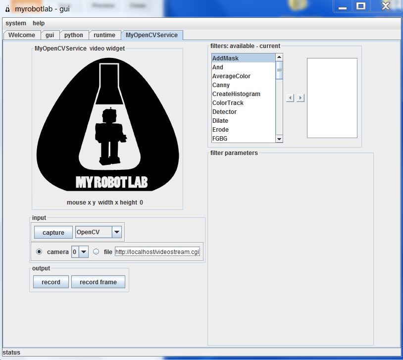
Next open MRL by clicking on the batch file and go to the runtime tab. Here you'll find a list of all the services MRL currently has to offer. Go ahead and scroll down to OpenCV. Right click on it to download and install it.

Then right click on it again and click start. It will want you to give it a name. Call it whatever you want. You do this so you can have multiple instances of the same service open if you want to.

Now you are come to the OpenCV GUI. It will default to camera 0. If you have multiple cameras connected, this might not be the one you want. Click capture to see what camera you have selected, and find the one you want.

Now we need to add our filters. First you need to scroll through and select PyramidDown. Either right click and add or select and hit the right arrow. Give it whatever name you want. PyramidDown makes the video smaller (you'll see). FaceDetect is pretty processor heavy, and unless you have a monster work station you'll want to use it. It will actually increase performance.

Next add the FaceDetect filter. Now click capture and go to town. You should see video in the box and a box drawn around any face. This is a good time to play around. The majority of the filters can be accessed through the GUI. See what filters help you isolate the face(or whatever you are trying to track). Try multiple PyramidDown filters or an InRange filter. Also note that if you right click in the display window, it will give you the coordinates in pixels. This is useful behavior.

Now I hit you with the bait and switch. It's not nice and GUI all the way to the end. Reason being, you need another service (the serial service) to actually get the data from your nice OpenCV box to your Arduino board. This requires you to use the python service.

The code really isn't that bad. I knew no python when I started working with myrobotlab. I still know very little, but I have pieced stuff together well enough from example sketches. You can look at the sketch below, but I would recommend you download it HERE.


# This code creates an opencv service and tracks a face.# It thens finds the center of the face and converts the position to a scale of 1-100# This information is then sent via serial service to any receiving device
# If the script needs to be restarted, completely close MRL and reopen it.# 8/27/13
import time
from java.lang import Stringfrom java.lang import Classfrom java.awt import Rectanglefrom org.myrobotlab.service import Runtimefrom org.myrobotlab.service import OpenCVfrom org.myrobotlab.opencv import OpenCVDatafrom com.googlecode.javacv.cpp.opencv_core import CvPoint;from org.myrobotlab.service import OpenCV
# create or get a handle to an OpenCV serviceopencv = Runtime.createAndStart("opencv","OpenCV")
# Convert the video to Black and Whiteopencv.addFilter("Gray1", "Gray")                             # Sometimes gray seems to help# reduce the size - face tracking doesn't need much detail. The smaller the fasteropencv.addFilter("PyramidDown1", "PyramidDown")# add the face detect filteropencv.addFilter("FaceDetect1", "FaceDetect")

#create a Serial service named serialserial = Runtime.createAndStart("serial","Serial")
# This function is called every time the OpenCV service has data available.# This will depend on the framerate of the video, but will probably be# somewhere around 15 times a second.def input():    global x    global y    global sposx    global sposy    global posx    global posy
    # Get OpenCV data    opencvData = msg_opencv_publishOpenCVData.data[0]
    if (opencvData.getBoundingBoxArray().size() > 0) :    # If the box surrounding a face exists     rect = opencvData.getBoundingBoxArray().get(0)       # Store the information in rect     posx = rect.x                                        # Get the x position of the corner     posy = rect.y                                        # Get the y position of the corner
     w = rect.width                                       # Get the width     h = rect.height                                      # Get the height     sposx = (w/2)     sposy = (h/2)     # Get the x and y of the center in pixels. Origin is in top left corner     x = (posx + sposx)
     y = (posy + sposy) 
     # Convert x,y pixels to (x,y) coordinates from top left.     # Note that 320 and 4240 will need to be changed if another pyramid down is used     # It may also need to be changed depending on your cameras specifications.     # This gets the position in a scale from 1, 100     x = int(translate(x, 1, 320, 1, 100));                  # translate() works the same way the Arduino map() function would     y = int(translate(y, 1, 240, 1, 100));     print 'x: ' ,  x                                        # print x to the python readout     print 'y: ' ,  y                                        # print y to the python readout     #write a series of bytes to the serial port     serial.write(250) # pan code     serial.write(x)   # x coordinate     serial.write(251) # tilt code     serial.write(y)   # y coordinate
 
#connect to a serial port COM15 57600 bitrate 8 data bits 1 stop bit 0 parity#This is what you want for an Arduino. Change the COM port to the one you are using.serial.connect("COM15", 57600, 8, 1, 0)#sometimes its important to wait a little for hardware to get readysleep(1)          # Note that this is 1 full second.
# create a message route from opencv to python so we can see the coordinate locationsopencv.addListener("publishOpenCVData", python.name, "input");
# Start capturing videoopencv.capture()  # Add a 1 inside the parenthesis to use camera 1


# Create function to scale values. Mimics Arduino map() function.def translate(value, leftMin, leftMax, rightMin, rightMax):    # Figure out how 'wide' each range is    leftSpan = leftMax - leftMin    rightSpan = rightMax - rightMin
    # Convert the left range into a 0-1 range (float)    valueScaled = float(value - leftMin) / float(leftSpan)
    # Convert the 0-1 range into a value in the right range.    return rightMin + (valueScaled * rightSpan)


Copy that into the python window and you're almost done. Towards the end you need to change the COM port to the one you are using. Below that, you will see opencv.capture(). If you are using a camera other than camera 0, put that number in the parenthesis.

Now connect your Arduino and click execute. You will see several readouts in the java window. The last one you should see should say
[opencv_videoProcessor] INFO  org.myrobotlab.opencv.VideoProcessor  - using com.googlecode.javacv.OpenCVFrameGrabber
That means you made it to the bottom of the script and you are getting video.

This is what is happening. The OpenCV service applies 3 filters: Gray, PyramidDown, and FaceDetect. It gets a box around the face and passes the coordinates in pixels to the python service. The python service finds the center of the box and the converts the pixel coordinates to a scale of 1-100 with the origin in the top left with positive down and to the right. The python service then passes the coordinates to the Serial service which connects to your COM port and begins sending x, y values across. It sends an identifier, then the value in the order below. Both the identifier and the coordinate are 1 byte in length.
  • 250
  • x coordinate
  • 251
  • y coordinate
What you do with those values on the Arduino side is up to you. That is why I used the serial service. It enables you to plug this system up to an existing Arduino project or any existing Arduino sketch and get vision processing data with nothing more that a Serial.read() and some if statements. Best of all, it is all in Arduino C, so anyone that has learned to program on an Arduino (like myself) can deal with the complicated stuff in a language they already know using the libraries that they already know.

I chose to make a pan-tilt camera mount that follows people, but like I said above, what you do with those (x,y) coordinates is really up to you. If you need help with serial communication, see my posts HERE and HERE. If you just want my pan-tilt Arduino code get it HERE. If you want the detailed description... wait until I write that post.

That's all I have. I plan on doing more specific examples in the future. For now, this should get you started. For more examples look at my labels. The one's labeled myrobotlab or vision processing will be the ones to check out. 

I hope this is of use to someone. I really do think myrobotlab is one of the best free, simple GUI system for OpenCV out there. It is fairly easy to use, and the support is great (just post on the site and ask for help). When I began using it, there was no serial service. I asked for one, and within a week GroG had added one.Who could ask for more?

Goodluck! May your frame rates always be high and your visions always be processed.
-Matthew