Showing posts with label Serial. Show all posts

Friday, October 18, 2013

Simple Face Tracking with OpenCV, myrobotlab GUI, and Arduino

In this post I will detail how to easily use OpenCV with an Arduino to detect and track a face. There are many methods out there, but this method gives you the best OpenCV GUIs that I have seen. Vision processing is never simple, but I think you will be pleasantly surprised.

First things first, I would probably get a lot more Google hits if my title said install OpenCV on Arduino. Many wayward Arduino users have traveled that road only to feel a little foolish when they realize just how impossible that is. An Arduino doesn't come close to cutting it in terms of processing power. There is a project porting OpenCV to a rasberrypi, but that is a different post. What we will be doing is using a computer to process video from a connected camera and then send the useful data to an Arduino in the form of (x,y) coordinates via serial. This is cool because it means that your Arduino can be connected via Bluetooth or USB and can do other things while the computer handles the heavy lifting.

The program that I will be using is called myrobotlab (MRL). I go into more detail in my Intro to myrobotlab post, but basically it is opensource, free, and in active development. When I set out to find an easy, GUI enabled OpenCV platform, this is what I found. While I have not done a full out comparison to ROS or RoboRealm, my general impression is that ROS is quite a bit more complicated, and RoboRealm is quite a bit more expensive (MRL is free). Regardless, you want a simple OpenCV, Arduino system. Let's go get one.

First you need to install myrobotlab. See the Quick Start section for instructions. Make sure you get the right version of Java. I seem to remember having some problems with that. If you do, post a comment or ask GroG on the site. I'd also recommend that you go ahead and create an account on myrobotlab.org. If you need help or have a question, that's where you need to be.

Next open MRL by clicking on the batch file and go to the runtime tab. Here you'll find a list of all the services MRL currently has to offer. Go ahead and scroll down to OpenCV. Right click on it to download and install it.

Then right click on it again and click start. It will want you to give it a name. Call it whatever you want. You do this so you can have multiple instances of the same service open if you want to.

Now you are come to the OpenCV GUI. It will default to camera 0. If you have multiple cameras connected, this might not be the one you want. Click capture to see what camera you have selected, and find the one you want.
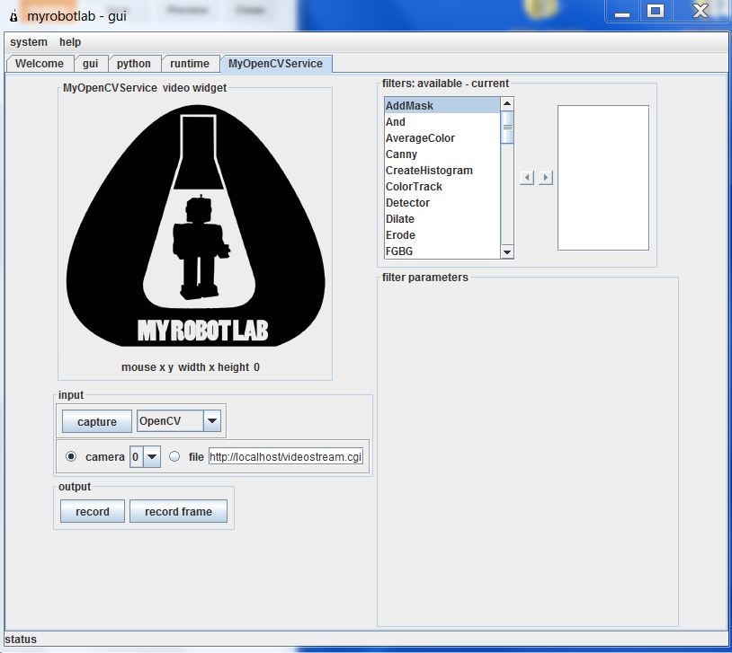
Now we need to add our filters. First you need to scroll through and select PyramidDown. Either right click and add or select and hit the right arrow. Give it whatever name you want. PyramidDown makes the video smaller (you'll see). FaceDetect is pretty processor heavy, and unless you have a monster work station you'll want to use it. It will actually increase performance.

Next add the FaceDetect filter. Now click capture and go to town. You should see video in the box and a box drawn around any face. This is a good time to play around. The majority of the filters can be accessed through the GUI. See what filters help you isolate the face(or whatever you are trying to track). Try multiple PyramidDown filters or an InRange filter. Also note that if you right click in the display window, it will give you the coordinates in pixels. This is useful behavior.

Now I hit you with the bait and switch. It's not nice and GUI all the way to the end. Reason being, you need another service (the serial service) to actually get the data from your nice OpenCV box to your Arduino board. This requires you to use the python service.

The code really isn't that bad. I knew no python when I started working with myrobotlab. I still know very little, but I have pieced stuff together well enough from example sketches. You can look at the sketch below, but I would recommend you download it HERE.


# This code creates an opencv service and tracks a face.# It thens finds the center of the face and converts the position to a scale of 1-100# This information is then sent via serial service to any receiving device
# If the script needs to be restarted, completely close MRL and reopen it.# 8/27/13
import time
from java.lang import Stringfrom java.lang import Classfrom java.awt import Rectanglefrom org.myrobotlab.service import Runtimefrom org.myrobotlab.service import OpenCVfrom org.myrobotlab.opencv import OpenCVDatafrom com.googlecode.javacv.cpp.opencv_core import CvPoint;from org.myrobotlab.service import OpenCV
# create or get a handle to an OpenCV serviceopencv = Runtime.createAndStart("opencv","OpenCV")
# Convert the video to Black and Whiteopencv.addFilter("Gray1", "Gray")                             # Sometimes gray seems to help# reduce the size - face tracking doesn't need much detail. The smaller the fasteropencv.addFilter("PyramidDown1", "PyramidDown")# add the face detect filteropencv.addFilter("FaceDetect1", "FaceDetect")

#create a Serial service named serialserial = Runtime.createAndStart("serial","Serial")
# This function is called every time the OpenCV service has data available.# This will depend on the framerate of the video, but will probably be# somewhere around 15 times a second.def input():    global x    global y    global sposx    global sposy    global posx    global posy
    # Get OpenCV data    opencvData = msg_opencv_publishOpenCVData.data[0]
    if (opencvData.getBoundingBoxArray().size() > 0) :    # If the box surrounding a face exists     rect = opencvData.getBoundingBoxArray().get(0)       # Store the information in rect     posx = rect.x                                        # Get the x position of the corner     posy = rect.y                                        # Get the y position of the corner
     w = rect.width                                       # Get the width     h = rect.height                                      # Get the height     sposx = (w/2)     sposy = (h/2)     # Get the x and y of the center in pixels. Origin is in top left corner     x = (posx + sposx)
     y = (posy + sposy) 
     # Convert x,y pixels to (x,y) coordinates from top left.     # Note that 320 and 4240 will need to be changed if another pyramid down is used     # It may also need to be changed depending on your cameras specifications.     # This gets the position in a scale from 1, 100     x = int(translate(x, 1, 320, 1, 100));                  # translate() works the same way the Arduino map() function would     y = int(translate(y, 1, 240, 1, 100));     print 'x: ' ,  x                                        # print x to the python readout     print 'y: ' ,  y                                        # print y to the python readout     #write a series of bytes to the serial port     serial.write(250) # pan code     serial.write(x)   # x coordinate     serial.write(251) # tilt code     serial.write(y)   # y coordinate
 
#connect to a serial port COM15 57600 bitrate 8 data bits 1 stop bit 0 parity#This is what you want for an Arduino. Change the COM port to the one you are using.serial.connect("COM15", 57600, 8, 1, 0)#sometimes its important to wait a little for hardware to get readysleep(1)          # Note that this is 1 full second.
# create a message route from opencv to python so we can see the coordinate locationsopencv.addListener("publishOpenCVData", python.name, "input");
# Start capturing videoopencv.capture()  # Add a 1 inside the parenthesis to use camera 1


# Create function to scale values. Mimics Arduino map() function.def translate(value, leftMin, leftMax, rightMin, rightMax):    # Figure out how 'wide' each range is    leftSpan = leftMax - leftMin    rightSpan = rightMax - rightMin
    # Convert the left range into a 0-1 range (float)    valueScaled = float(value - leftMin) / float(leftSpan)
    # Convert the 0-1 range into a value in the right range.    return rightMin + (valueScaled * rightSpan)


Copy that into the python window and you're almost done. Towards the end you need to change the COM port to the one you are using. Below that, you will see opencv.capture(). If you are using a camera other than camera 0, put that number in the parenthesis.

Now connect your Arduino and click execute. You will see several readouts in the java window. The last one you should see should say
[opencv_videoProcessor] INFO  org.myrobotlab.opencv.VideoProcessor  - using com.googlecode.javacv.OpenCVFrameGrabber
That means you made it to the bottom of the script and you are getting video.

This is what is happening. The OpenCV service applies 3 filters: Gray, PyramidDown, and FaceDetect. It gets a box around the face and passes the coordinates in pixels to the python service. The python service finds the center of the box and the converts the pixel coordinates to a scale of 1-100 with the origin in the top left with positive down and to the right. The python service then passes the coordinates to the Serial service which connects to your COM port and begins sending x, y values across. It sends an identifier, then the value in the order below. Both the identifier and the coordinate are 1 byte in length.
  • 250
  • x coordinate
  • 251
  • y coordinate
What you do with those values on the Arduino side is up to you. That is why I used the serial service. It enables you to plug this system up to an existing Arduino project or any existing Arduino sketch and get vision processing data with nothing more that a Serial.read() and some if statements. Best of all, it is all in Arduino C, so anyone that has learned to program on an Arduino (like myself) can deal with the complicated stuff in a language they already know using the libraries that they already know.

I chose to make a pan-tilt camera mount that follows people, but like I said above, what you do with those (x,y) coordinates is really up to you. If you need help with serial communication, see my posts HERE and HERE. If you just want my pan-tilt Arduino code get it HERE. If you want the detailed description... wait until I write that post.

That's all I have. I plan on doing more specific examples in the future. For now, this should get you started. For more examples look at my labels. The one's labeled myrobotlab or vision processing will be the ones to check out. 

I hope this is of use to someone. I really do think myrobotlab is one of the best free, simple GUI system for OpenCV out there. It is fairly easy to use, and the support is great (just post on the site and ask for help). When I began using it, there was no serial service. I asked for one, and within a week GroG had added one.Who could ask for more?

Goodluck! May your frame rates always be high and your visions always be processed.
-Matthew

Wednesday, August 7, 2013

Serial Sonar Sensor: ATtiny85, HC-SR04, and Arduino SoftwareSerial

In this post I will detail how I used an ATtiny85 as a controller for an HC-SR04 sonar module (Ping sensor). The controller reads the inputs from up to 3 HC-SR04 modules and transmits the readings to an Arduino Mega via serial communication. This allows the Arduino Mega to pick up the readings whenever it is convenient rather than having to worry about complex timings. Let's get started


First things first, we need to run the NewPing library on an ATtiny85/45/25. Until version 1.6 is released you will need to modify the library to do this. However, this removes some of the functions you might want to use on other boards. For this reason, I created the TinyNewPing Library. In it, I removed the parts that cause the errors on an ATtiny and gave it a new name so you can distinguish between the two. All the function names remain the same. If you still need more details check out THIS prior post.

Next we need the SoftwareSerial Library on the ATtiny. Luckily, this comes with the IDE and I already did a post on it. Funny how that works.

For a first attempt, try a single HC-SR04 sonar sensor. This simplifies the code a bit. Load THIS code on the ATtiny (sensor side) and THIS code on the Arduino Mega. Note the code uses both Serial and Serial1 (thus the Arduino Mega).

To wire it up, connect the echo and trigger pin together and then connect them to pin 0. Wire in 5V and ground to both the ATtiny and the HC-SR04. Then connect pin 4 (Software Tx) on the ATtiny to pin 19 (Rx1) on the Mega. Finally, plug the Mega into the computer via USB.

Now if this is working ok, we can move on to 3 sensors. For that, we need to load THIS code onto the ATtiny and THIS code onto the Arduino Mega. The ATtiny takes the readings and sends them to the Mega. The Mega updates it's variables and sends them to the Serial Monitor for us to see.

Wiring it is cumbersome but simple. Regrettably, I did not take a picture when I did it, but just do what you did before an extra two times. Note again that we are using the same pin for trigger and echo, so they need to be wired together. Then wire up power and grounds. Finally connect the ATtiny to the Mega and the Mega to the computer.

Now open the Serial Monitor and watch the numbers scroll by.

Potential problems: If the ATtiny gets out of sync with the Mega (it will), an occasional bad value will come up. I couldn't come up with a quick fix for this. If that is a problem, maybe you could take the median of a few readings. They are coming in pretty quickly. The plan is to make an I2C version of this soon, but I make no promises on a deadline. One last download, get the entire package of sketches used in this post in a zip file HERE.

A few quick notes before we go.

  • Why not I2C? That's next (Done! Check it out HERE). Serial is easier because it doesn't require a 3rd party library to work on the ATtiny line. 
  • Why only 3 sensors? Short answer, ease of use. You might be able to get 4 or even 5 out of an ATtiny45 if you're persistant. I don't have that many sensors nor that much patience. You have 5 regular IO pins plus the reset pin (which can be used as an IO). You might be able to use the serial Rx pin as an input as well. 
  • Why not just buy a I2C ping sensor and be done with it? Well this reduces the number of wires going to the Arduino Mega. It also gives you more options and increases the number of micro controllers on board your robot (cool factor). Other than that, it's cheap. With HobbyKing or Ebay, this project could be done for less than the price of one I2C sonar sensors.
Hopefully someone will find this useful. If anything goes great, please comment! If anything goes wrong, contact your local internet service provider. I blame them (That's a joke. You can comment below as well).

-Matthew

Thursday, June 13, 2013

Serial Communication on a ATtiny85 with the SoftwareSerial Library.

"Serial is giving me errors on my ATtiny! What can I do?" We have a solution.

Serial communication is not difficult on an ATtiny thanks to the SoftwareSerial Library. While the ATtiny85 does not have the hardware of a "real" Arduino, it can still function in similar fashion. If you're just getting started with using an ATtiny, here are some resources you might need.

  • Information on programming them from High-Low Tech. You can also look back at my previous posts.
  • My nifty programming adapter. A few minutes of soldering made my life much easier.
  • My USBtinyISP is discussed in THIS post. It also makes life easier.
  • Previous posts on Running Servos and the NewPing Library on an ATtiny.
  • THIS previous post mentioning my USB to UART converter cable
Now we are ready to go. First things first, I am using Arduino 1.0.4. The SoftwareSerial Library is included as a default library, so there is no reason to get a 3rd party library.


Step One: Wire it up. With my USB to UART cable it is as follows.
  • Black: Ground
  • Green: Tx (using Tx as pin 4)
  • White: Rx (using Rx as pin 3)
  • Red: 5v (this is optional if you have an external power supply)
Connect an LED with appropriate resistor to pin 1.

Step Two: Ensure that your ATtiny is burned to run at 8MHz. Now load THIS sketch onto the ATtiny. Note that parseInt() works with the SoftwareSerial Library.

Step Three: Open the Serial Monitor and set it to the correct Baud rate. To reset the ATtiny, bridge the reset pin to ground momentarily. When you see the connected message, enter an integer and count the flashes.

That's all there is to it. I you don't have a USB UART cable, this is easily adaptable to communication with another Arduino with a USB port. See THIS post for code. If you want to see a practical application of serial communication on an ATtiny85, check out my serial sonar controller HERE.

Hope this works for you all. As usual, if there are any questions, just let me know.
-Matthew

Tuesday, June 11, 2013

Multiple Simultaneous Serial Communications

As I mentioned in an earlier post I have an Arduino Mega with a broken USB to serial chip. With that in mind, I thought it would be useful to have an external USB to UART cable. Mine was $4 on Ebay. When it arrived I set to work ringing it out to make sure it worked. Here are the results.

Because my "broken" Arduino is still on my robot, I just used my working one. It is a supposedly identical Arduino Mega 2560 R3. As I played with this I realized that I could communicate with 2 ports simultaneously now (or 3 if I broke out my Bluetooth again). Why is this useful? It's not at the moment. This is really pretty simple, so this will be a short post.

Step One: Wire it up. With my cable it is as follows.

  • Black: Ground
  • Green: Tx (using Tx1 pin 18)
  • White: Rx (using Rx1 pin 19)
  • Red: 5v (this is optional if you have an external power supply).
It is worth noting that my cable does not allow for auto reset. This means that it is pretty difficult to load new programs to the Arduino with the default bootloader. 

Step Two: Load program on Arduino. This very simple. HERE is my example. When you're done, leave the USB plugged in.

Step Three: Open the Serial Monitors and watch for the messages. You will either need to use another program like Tera Term as mentioned in THIS post, or you can open two windows of the Arduino IDE.

That's all there is to it. Now you can communicate with the computer via two serial ports "simultaneously." If you need more information on Serial communications check out THIS post. I also have a post on I2C communication as well as Bluetooth.

-Matthew

Friday, June 7, 2013

Arduino Bluetooth with a HC-06 and JY-MCU

With the arrival of my Bluetooth module I decided to give wireless communication another try. I'm glad I did. Setting up my Bluetooth module for wireless communication took less than an hour. While I have not explored it very in depth yet, I can see myself getting some use from this module. It becomes a generic wireless COM port. I have even read about uploading sketches via Bluetooth if you use a custom bootloader. I will probably never delve into that, but let's get started with the basics.

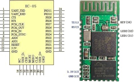
When I first ordered my Bluetooth module, I got a "Bluetooth Serial Transceiver Module Base Board with Enable function For Arduino" from Ebay. I payed a few dollars for it only to realize when I got it that the board was merely a breakout (called a JY-MCU) for another board. Another purchase later, and I had all the things I needed to get going. I got an HC-06 (aka "New Mini 3.3V wireless Bluetooth Transceiver Slave Module Serial Port 30ft TTL"). There is also an HC-05 which apparently is very similar (it seems to share the same pinout).


HC-05 pinout
First things first, I soldered my HC-05 onto the JY-MCU. These can be purchased already soldered for less than $10, but the soldering was good practice. I held the module in place with double sided tape and a piece of tape around the end while I soldered it. The contacts aren't too small, but you will need a decent soldering iron with a small tip.
My impressive soldering


Next I wired it up. This is the point where I began calling on the collective knowledge of the internet. Follow THIS Instructable. With a few changes, it is what I did. For the voltage divider I used a 2.2k Ohm and a 1k Ohm + 100 Ohm resistor. It worked fine. I checked it with the volt meter and it came out to about 3.1v. HERE is the voltage divider calculator I used. Be sure you use that on the Bluetooth Rx/ Arduino Tx side or else you could fry your Bluetooth module. The ATmega 2560 will accept 3.3v so the Arduino Rx is fine by itself (sort of. I wouldn't put this on anything too important, but worst you will get false data). Someday I'll get a real logic level converter. For convenience, I used the Serial1 pins on my Arduino Mega 2560.

Now you need to load a test sketch onto your Arduino. I used the one on the Instructable (with Serial changed to Serial1). To do this you will probably need to unplug the Arduino Rx pin. Should we have loaded the program before wiring like the Instructable said? Probably. Oh well. Take this opportunity to double check all wiring and ring them out with a volt meter.

Now we need to connect the HC-06 Bluetooth module to the computer. I am running Windows 7, and this took about 3 minutes. The steps are on the Instructable, but I would feel bad if I didn't post all the screenshots that I took. Power up your Bluetooth module and follow the steps below.

1) Find the Bluetooth Icon in the bottom right hand portion of the screen. Right Click and Select "Add a Device." My device was called linvor. Whatever floats their Chinese boat. The password for mine was 1234. If that doesn't work, try 0000.


2) Go to Devices and Printers and see if it appears. Wait for Windows to install all necessary drivers. note what COM port it is using. Mine uses two apparently.. Oh well. Not worth the energy to worry about it.


3) Download a terminal emulator program. "Can't I just use the Serial Monitor???" No. Only one device can use a serial port at a time. That is why the Serial Monitor shuts down when you upload a sketch. "Then what should I use???" Well I used Tera Term like the Instructable said because it was the least confusing to a simple mind like me. PuTTy and RealTerm are probably more popular choices. I haven't explored them. I'll assume you use Tera Term.

4) Connect to the module in Tera Term. This is super simple. Select the right COM port.


5) Bask in the beauty of the numbers streaming by. 


This took all of an hour for me. I was astonished at how painless it was, especially compared to my struggles with the nRF24L01+. I am not sure what I will do with it now (I have some ideas). I hope you all have the same success I did. If you need the sample sketches for some reason, they are HERE.

Best of luck,
-Matthew


Saturday, May 11, 2013

Arduino: Serial Communication Between Two Arduinos

I wanted to know more about inter-Arduino communication, so I did this project. I want to explore the different ways to communicate with and between Arduinos.

First up is serial communication. This is pretty simple. I expected there to be more hitches, but it turned out to be pretty straight forward. Well let's get to it.

First things first, HERE is the Arduino playground page for serial communication. You might want to read up on the different commands you have there.

Ok, first program. One Arduino transmits one integer every second counting from 1 to 10. The receiving Arduino then prints that number to the COM port where I can see it.  I only have one Arduino with a working USB to serial interface, so I used it as the Rx.

The code is simple enough. You can get mine HERE, but I would encourage anyone to try to write it yourself. It helps, and this is short enough. The only unexpected detail is the parseInt(). I first tried a simple read(). Well that doesn't work because that displays the ASCII character and not the integer value. I had forgotten that.

To wire it up, simply connect Tx (probably pin 1) of the Tx board to the Rx (probably pin 0) of the Rx board. Then connect a common ground between the two. Note that you may need to connect these pins after you load the program on the Arduino (since you are using that pin to communicate with the computer via the USB to serial chip). Leaving them connected caused an error for me. This might be avoided if you put a resistor in between the 2 boards, but I have not tried. By the way, if you're wondering where I got that super cool Tx Arduino, check out THIS post. It was really cheap fun!

Left: Rx                         Right: Tx
Well that was cool. Now I want to go the other way. The next program blinks the LED on the Rx board a specific number of times entered through the Serial Monitor connected to the Tx board.

The code again is not that difficult. HERE is mine. Again, use parseInt() and you're golden.

The wiring is equally simple. It's the same as you just did except in reverse the two boards. In fact, if you had two "real" Arduinos with an FTDI or similar, you wouldn't even need to do that. Just make sure you wire in the common ground as always.

Left: Tx                       Right: Rx

Well that's great and all, but I want to communicate both ways. Next program. This one takes an integer value from a user input through the Serial Monitor and then sends it to the Rx Arduino. The Rx then adds 5 to the integer an sends it back to the Tx. Note that the Tx and Rx labels are a bit arbitrary in this one. It's more of a master-slave relationship.


HERE is my code if you want it.


Wiring is similar to above. However, I used Serial1 on the Tx to communicate with the Rx board. This just kept the USB communication from interfering. This functionality is only available on the Arduino Mega as far as I know (besides 3rd party boards). See the Arduino Documentation linked at the beginning of this post for more details. It's also interesting to note that I noticed I didn't need to power the Rx board for it to work. It would draw power from the Tx pin. That was interesting. I powered it anyway.


Ok.  Last program. This one only uses one Arduino. It allows you to input a word , and it mirrors it back to you. Now this is not all that impressive in itself, but it is still very useful.

There are only a few major changes to the code we have been using. We need to make the variables we use char variables. Also we need to change the parseInt() to a plain read(). Another note, remember that serial is one bit at a time. So if you want to do a line return, you need to handle that yourself. I made it do one every time it saw a period. \n would be more traditional, but that was more work.

HERE is my program. It is pretty simple, but I am not a programmer. If your program is doing anything else you will probably want to use a char string. THIS looks like a good example of this.

Wiring nonexistent. Just connect your Arduino via USB.

That's all I have for now. Hope this was useful! If you want the full package of programs you can get them in zip HERE. Also, if you want to learn about serial communication with an ATtiny (a $2 microcontroller) check that out HERE. If you are looking for something else, try my communication label. There may be something in there that will interest you.

-Matthew