Showing posts with label Purchases. Show all posts

Friday, November 1, 2013

KY3361ABR-242 Mini Volt Meter

This is a mini review for a volt meter I picked up off eBay a while ago for about $1.50. I don't know that it has a name, so I have decided to call it the KY3362ABR-242 Mini voltmeter. I suspect KY3362ABR-242 actually refers to the display, but regardless it is written on the bottom of the volt meter. That is what I am calling it. As you can see in the pictures, V1303 and DV036A are also printed on the back, but I am ignoring those.

Not a whole lot of information was given with this purchase, but what the seller offered I saved for posterity below.
Specifications:
  • Measuring range: DC 0V--30V
  • Input range: DC 2.5V-30V (Max Input: DC 30V. The device can be damaged if input is over 30V)
  • Display Color: RED
  • Display: Three 0.36 "digital tube
  • Measurement accuracy: 0.1%
  • Refresh rate: about 300mS / times
  • Input impedance: About 100K
  • Dimensions:33mm*15mm*10mm
  • pitch of holes:28mm
  • aperture size :2.8mm
  • Operation Temp: -10℃-+65℃
Wiring:
  • red:power supply +
  • black:power supply -, measure -
  • white:measure +


I soldered on some nice male headers with some heat shrink and got to testing. Here are the photos.

Measuring the 3.3 V supply from my MB-102 power supply

Measuring the 5 V supply from my MB-102 power supply

Measuring the 5 V supply from my Arduino Mega powered over USB.

As you can see, the mini voltmeter consistently read close to the same thing that my craftsman meter read. Granted that is not the best benchmark, but it is what I have. It is also interesting to note that the KY3362ABR-242 can even measure the power supply from which it is being powered.

All in all, this is a very nice little purchase. I would definitely pick one up if you have a need. It is not going to replace your multimeter, but it is a very nice real time display for breadboard power supplies or similar. You can also do cool stuff like hack it into an I2C display.


Tuesday, July 16, 2013

Deer Defense System: PIR motion sensor

Today I will provide information necessary to build a Deer Defense System (DDS). The specific plans I will be using were leaked from an undisclosed source at the DoD and are highly classified. Continue reading at your own risk.

This summer has been a unique adventure at the family garden. First, for whatever reason our squash have grown huge this year. Second (and more relevant), the deer have been particularly aggressive and determined.

For those of you that may not know, in certain areas of the Southern United States white-tailed deer (Bambi) are quite prolific. What may be less known is that these deer love to eat bean plants and will tolerate eating squash, tomatoes, cucumbers, and anything else you don't particularly want eaten. I can vouch for this from experience. Feast your eyes on the destruction.

Well we explored several more traditional methods of repelling deer. We tried all sorts of smelly concoctions. Some worked until it rained. Planting garlic did not help. Marigolds and mothballs did not help. The .30-06 did not work (We didn't try. Deer are out of season. Babies). They sell motion activated sprinklers that would probably work, but they are $50 a piece. No dice.

Having too much free time, I set about making a motion activated deer scaring device (these plans weren't really stolen from the DoD). Here is an overview.

At the heart of the matter is a Pyroelectric InfraRed  sensor. Mine was purchased from Ebay for $1.98. It does work, but be warned, when I asked for the datasheet they said it was a "trade secret." Right. Several other vendors carry them. For details on how to use a PIR sensor see THIS link. Basically, a pin goes high when it senses motion.


 My sensor had several adjustments on it. I found the picture on the left that tells what everything does. By wiring up an LED as discussed in the link above, I then found the settings that worked best for me.

After getting my motion sensor working I had to decide what brains to put in it. I considered another ATtiny45 , but decided to try something simpler first. I just hooked a transistor to the output of the sensor and used it to turn on a bright LED and sound a buzzer. 


Now the biggest concern I have here is the power consumption. I am powering the entire thing on 3 AA batteries. I read online that most of these PIR sensors use about 1.2 mA while on idle. I need a way to shut it down during the day (deer eat gardens after dark). Basically I want a nightlight circuit. 

I had a photo-resistor, but unfortunately the only transistors I had were NPN. This led me to use THESE plans to turn on the power to the PIR sensor only when it is dark outside. When it is light, it supposedly uses in the realm of .1 mA. With this addition, the DDS should last a month or so depending on how often the alarm goes off. Below is a rough diagram of what I built. The circuitry on the left turns on the power at night. The stuff on the right scares the deer.
The switch is the PIR sensor
I soldered everything together and hot glued it into a nice watertight container. Now it is ready to go. I don't know if it will actually scare off the dear or not. I suspect it will not do too much. Regardless, it was a fun project. I hope you enjoyed it!

-Matthew 


Friday, June 7, 2013

Arduino Bluetooth with a HC-06 and JY-MCU

With the arrival of my Bluetooth module I decided to give wireless communication another try. I'm glad I did. Setting up my Bluetooth module for wireless communication took less than an hour. While I have not explored it very in depth yet, I can see myself getting some use from this module. It becomes a generic wireless COM port. I have even read about uploading sketches via Bluetooth if you use a custom bootloader. I will probably never delve into that, but let's get started with the basics.

When I first ordered my Bluetooth module, I got a "Bluetooth Serial Transceiver Module Base Board with Enable function For Arduino" from Ebay. I payed a few dollars for it only to realize when I got it that the board was merely a breakout (called a JY-MCU) for another board. Another purchase later, and I had all the things I needed to get going. I got an HC-06 (aka "New Mini 3.3V wireless Bluetooth Transceiver Slave Module Serial Port 30ft TTL"). There is also an HC-05 which apparently is very similar (it seems to share the same pinout).


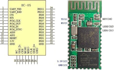
HC-05 pinout
First things first, I soldered my HC-05 onto the JY-MCU. These can be purchased already soldered for less than $10, but the soldering was good practice. I held the module in place with double sided tape and a piece of tape around the end while I soldered it. The contacts aren't too small, but you will need a decent soldering iron with a small tip.
My impressive soldering


Next I wired it up. This is the point where I began calling on the collective knowledge of the internet. Follow THIS Instructable. With a few changes, it is what I did. For the voltage divider I used a 2.2k Ohm and a 1k Ohm + 100 Ohm resistor. It worked fine. I checked it with the volt meter and it came out to about 3.1v. HERE is the voltage divider calculator I used. Be sure you use that on the Bluetooth Rx/ Arduino Tx side or else you could fry your Bluetooth module. The ATmega 2560 will accept 3.3v so the Arduino Rx is fine by itself (sort of. I wouldn't put this on anything too important, but worst you will get false data). Someday I'll get a real logic level converter. For convenience, I used the Serial1 pins on my Arduino Mega 2560.

Now you need to load a test sketch onto your Arduino. I used the one on the Instructable (with Serial changed to Serial1). To do this you will probably need to unplug the Arduino Rx pin. Should we have loaded the program before wiring like the Instructable said? Probably. Oh well. Take this opportunity to double check all wiring and ring them out with a volt meter.

Now we need to connect the HC-06 Bluetooth module to the computer. I am running Windows 7, and this took about 3 minutes. The steps are on the Instructable, but I would feel bad if I didn't post all the screenshots that I took. Power up your Bluetooth module and follow the steps below.

1) Find the Bluetooth Icon in the bottom right hand portion of the screen. Right Click and Select "Add a Device." My device was called linvor. Whatever floats their Chinese boat. The password for mine was 1234. If that doesn't work, try 0000.


2) Go to Devices and Printers and see if it appears. Wait for Windows to install all necessary drivers. note what COM port it is using. Mine uses two apparently.. Oh well. Not worth the energy to worry about it.


3) Download a terminal emulator program. "Can't I just use the Serial Monitor???" No. Only one device can use a serial port at a time. That is why the Serial Monitor shuts down when you upload a sketch. "Then what should I use???" Well I used Tera Term like the Instructable said because it was the least confusing to a simple mind like me. PuTTy and RealTerm are probably more popular choices. I haven't explored them. I'll assume you use Tera Term.

4) Connect to the module in Tera Term. This is super simple. Select the right COM port.


5) Bask in the beauty of the numbers streaming by. 


This took all of an hour for me. I was astonished at how painless it was, especially compared to my struggles with the nRF24L01+. I am not sure what I will do with it now (I have some ideas). I hope you all have the same success I did. If you need the sample sketches for some reason, they are HERE.

Best of luck,
-Matthew


Tuesday, June 4, 2013

Arduino RTC: TinyRTC v1 with Arduino Mega 2560

This post is slightly out of sync with my previous ones. I was digging around in my parts box and found my real time clock (RTC) module, a TinyRTC v1. I then realized that I had not posted any of my findings when I used it. Well I had a few minutes today, so I decided to dust off the RTC and see if it was still working.

A real time clock is something many new hobbyist might take for granted. Living in a world of computers with integrated RTCs and internet connections, it's easy to forget just what it takes to keep track of the time. While any Arduino can give you the time since it's last restart (or pretty close to it anyway). To keep track of the time displayed on your cuckoo clock you will need some external hardware and a continuous power supply. Various people have come up with  good combinations of said hardware, and all you need to do is buy a RTC module.

The module I will be using is a Tiny RTC v1 module. They are commonly found on Ebay called "Real Time Clock DS1307 I2C AT24C32" or similar. Communication is done over an I2C interface. It has a battery on-board that can supposedly last for several years.

I didn't really remember how I set up the RTC, so I started digging around. I found 2 sketches that I picked up from somewhere. I believe the Ebay seller posted them. I tried them out, and they do work as expected. SetRTC sets the RTC with a time you hardcode into the sketch. GetRTC simply displays the time given from the RTC. Both sketches require the Wire library and the I2C address. To find the I2C address, use THIS I2C scanner.

First wire it up. Connect SCL and SDA to the appropriate pins (21 and 20 on the Arduino Mega 2560). Connect Vcc to 5v and GND to GND. Ignore the rest of the pins. To the right is a diagram of the connections for an Uno if you are confused. Next set the time in the function and upload SetRTC to your Arduino. Then hit the reset button at the moment you want to set the clock.

Now we can upload the GetRTC. Open the Serial Monitor and watch the seconds tick by. An interesting note, if you unplug the GND and reattach it, the time gets corrupted, and you will have to reset the time.

Now, while this method works, I would be remiss if did not mention the Time library. It has many other functions that may be useful depending on your situation. I have not explored them, but I assume it works well. To set the time using the library you will need to download Processing. By using a Processing sketch, you can sync the clock's time to that of your computer.

That's all for today. Go forth and make data loggers, binary clocks, and other exciting projects.
-Matthew

Thursday, May 30, 2013

Stepper Motors and Arduino: 28BYJ-48 with ULN2003

Today I will be exploring the world of stepper motors. I recently purchased a 28BYJ-48 stepper motor with a ULN2003 controller. They are available from a host of vendors for a few dollars and seem to be pretty popular in the Arduino community.

Getting started, there are several links you might find useful.

  • Basic information on the motor and controller as well as a sample sketch using the standard Stepper library.
  • The Stepper Library- This is the library that is included with the Arduino IDE. This library is set up to run a stepper without a gearbox, so it would have to be modified.
  • Stepper2.ino- This sketch includes a full set of functions that can be used to run the 28BYJ-48. It is discussed on THIS page, but it appears that the plans to convert it into a "real" library were never implemented. 
  • Custom Stepper Library- This library can be used to control a variety of steppers, but the default settings are for the 28BYJ-48
First I just wanted to get the stepper turning. I found THIS forum thread with some basic code to get it running. HERE is the code. It is very basic and does work. If you read THESE notes and still didn't understand how steppers work. This sketch might clear it up for you. Below is a video of the sketch working. 

Note how it is wired. You don't want to power the stepper from the Arduino. It can pull 90mA which is a lot for your little Arduino. I used my nifty breadboard power supply that I picked up for a few dollars on Ebay. Power goes to the left 2 male pins on the ULN2003 breakout (marked - + 5-12V). The jumper on the right just switches power to the motor. Removing it opens the circuit between the + power supply and the motor. Other than that, just use some female-female jumpers to connect the inputs to the whatever pins you are using on the Arduino. I am using an Arduino Mega 2560 with an Arduino sensor shield v4, so this is very easy to do. For those that don't know, the ULN2003 is just a little Darlington Array that allows us to switch power from an external source on and off rather than using the Arduino's on board power supply.

Next I decided that I would try the Arduino Stepper library first. While Stepper2 looks promising, I wanted something actively supported. Luckily THIS wiki provides code for using the standard library. HERE it is again, saved for posterity. I will note that 4096 steps resulted in 2 revolutions. Also, at the default steps/revolution 300 appeared to be a good maximum speed. 400 would not run at all. When I changed the steps/revolution to 2048, 10 worked well as a max. Another useful thing to know, the clockwise and counter-clockwise directions are defined when looking at the motor from the back (the side with the label). That is, from the perspective I used in the video above it will be backwards. 

If it is not working try some of the things below. If those don't help, Google the problem. If all else fails, comment, and I will see what I can do.
  • Reduce the speed. These motors only turn so fast before they bind up and stop moving.
  • Check the motor's temperature. The top speed of mine seemed to depend a bit on how warm it was.
  • Check wiring. Make sure your Arduino is hooked up correctly and you have defined the right pins in your code.
  • Check the jumper on the ULN2003 control board. It must be in place (bridging the right two pins).
Well that's about all I have at the moment. I have not dug into the other two stepper libraries I listed. I just wanted to do an intro so I could add stepper motors to my robo-arsenal. If I do any projects with them I will post about it.

-Matthew

Friday, April 26, 2013

Breadboarding a Surface Mountable ATtiny85

I previously mentioned, I recently made a purchase from Mouser.com. Today I wanted to make a quick post about one of my purchases.

I had planned on ordering a few ATtiny85's when ordered the stuff for my ATmega328 breakout. Unfortunately, the dip package was out of stock, so I did the next best thing. I ordered a few ATtiny45's and some surface mountable ATtiny85.

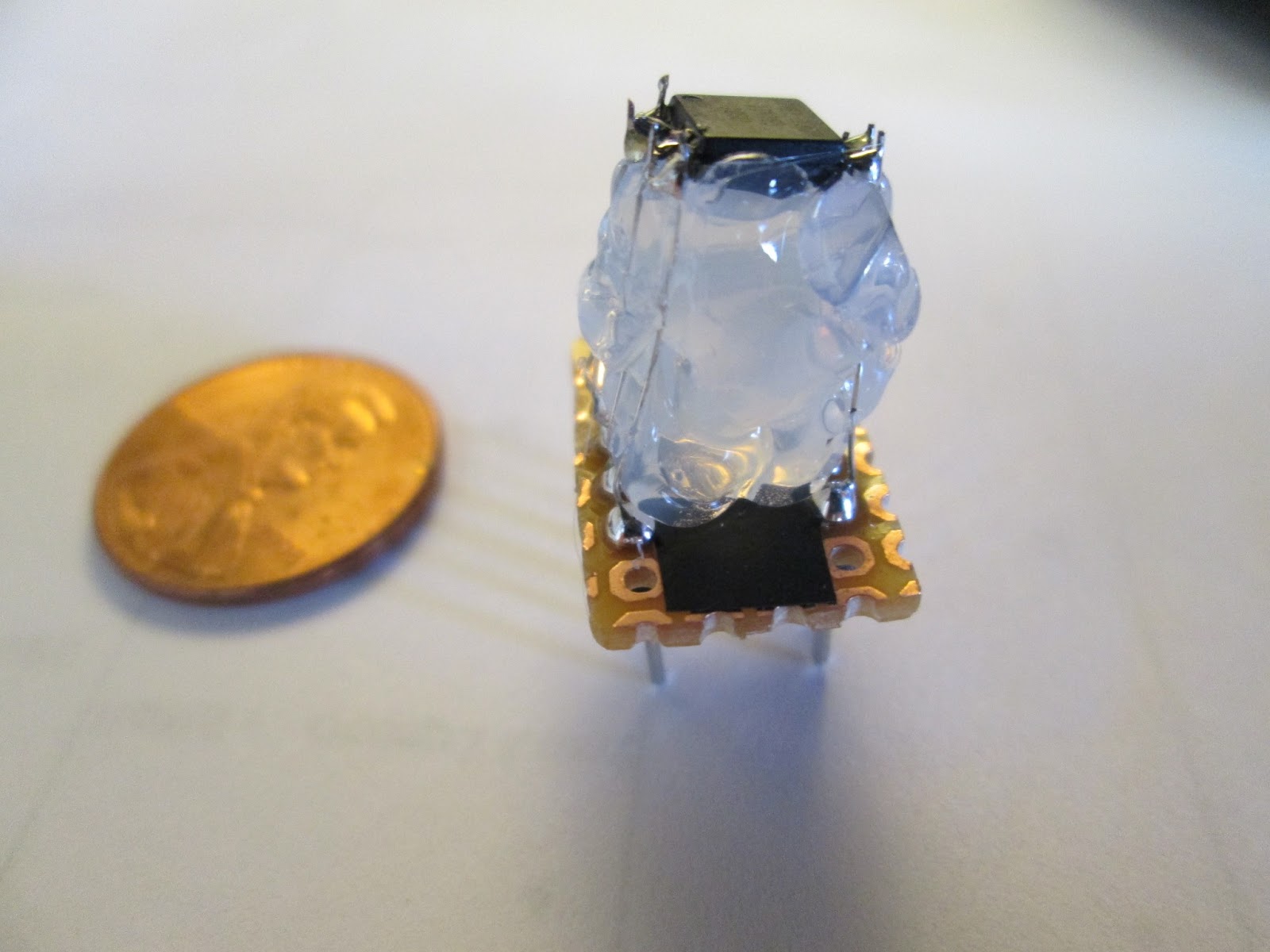
ATtiny85-20 SU vs SH
They had two that caught my eye. ATtiny85-20SU and the ATtiny85-20SH were $0.83 and $1.18 respectively. Honestly. I had no clue what the difference was, so I ordered a couple of each.

I received them and finally set about playing with them a few days ago. To the right you see a picture of the two different kinds. Don't let the picture deceive you. They look the same. I'm not an expert on such things. If someone knows what those letters mean let me know and I'll update this post.

UPDATE: Jason the PC MD says that the pins are made of different materials. This would make sense. Tin is cheaper.
SH:NiPdAu
SU: Tin

Regardless, I wanted to put them on a breadboard to play with. There are several ways to do this. Ideally, I would make a little PCB and solder it together. Maybe someday I will get into etching, but that day is not today. I have also heard of surface mounting protoboard which has smaller spacings to accomodate surface mounted parts. I'm sure there are other methods as well (I saw something about drawing with a conductive pen.. Not going there). Anyway, I had none of these methods available, so I broke out the soldering iron and went to town.

I started with a small piece of protoboard that I cut to size with an x-acto knife and sanded smooth.


Next I snapped off some male headers and placed them in a solder-less breadboard to insure they stayed straight. I randomly decided that I would use an ATtiny85-20SU and then began to very carefully solder each pin to the corresponding header. I used the same small Kynar wire that I used for my ATtiny programming adapter (which if you haven't seen, you should check out. It makes my life much easier when I program the ATtiny DIP sockets).


When I got done I squirted a good bit of hot glue under the ATtiny itself just to make sure it didn't move around and short out. I also super glued the headers to the protoboard because the pins aren't plated all the way through on this cheap protoboard, and I didn't want them to pull off with repeated use.


I have no doubt that this could be done more compactly. This is not pretty and won't work with my previously mentioned adapter, but it gets the job done. I have tested it; it works fine. As for SH vs SU mounting types, I still don't know. We will see what time reveals.

Also, this weekend is the FIRST Robotics Championship in St. Louis. If you don't know what that is, check out the website usfirst.org. The competition will be streaming live as well. That can be found HERE. I know from first hand experience that it is a lot of fun. If you ever get the chance to go to one of the events, you won't regret it. They are all free and open to the public.

-Matthew