Showing posts with label Libraries. Show all posts

Saturday, November 4, 2017

Querying SQLite database using sqlite3 in JavaScript

Motivation

I've never regretted studying mechanical engineering instead of electrical engineering or computer science, but sometimes by lack of formal programming knowledge does bite me. This happened a few days ago when I wanted to see if I could apply some machine learning techniques to some data in a SQLite database. Having no experience with SQL and minimal experience with javascript, I Googled how to get the data. The answers that I found seemed overly complicated. As such, this post will be a practical example of  querying the data from an SQLite database. It is as much for my memory as anything. I was using JavaScript (via Node) and sqlite3. I did this on a Virtual Machine running Ubuntu, but I believe all of the tools I use can be used in Windows as well.

Data Visualization using SQLiteStudio

Here is a visualization of the data. It is some historical trade data from the cryptocurrency exchange,  Poloniex. Having never used SQL before, I downloaded SQLiteStudio to see what the data actually looked like. As you can see, the database contains two tables - in this case one for each of the two trading pairs for which I had data. Inside those tables, there are labeled columns. Each row has a unique id. 


Querying the Database using sqlite3

I found a tutorial (THIS ONE) and tried to follow it, but I found that it took a frustratingly long amount of time to figure out what all of the values meant. Anyway, here is my javascript code to query a single line from the database. If you understand this, the above tutorial should be easy to adapt to pulling multiple lines. Of course, you need to already have sqlite3 installed. 


//Import sqlite to read database
const sqlite3 = require('sqlite3').verbose();
//Connect to database
let db = new sqlite3.Database('./history/poloniex_0.1.db', (err) => {
  if (err) {
    console.error(err.message);
  }
  console.log('Connected to the database.');
});


// get columns start and label it as startval, open-> openval, etc from the appropriate table
// when the id = what we define it as below
let sql = `SELECT start startval,
                  open openval,
                  high highval
           FROM candles_USDT_ETH
           WHERE id = ?`;

let id = 2;
 
// Get only [id] row (in this case 2nd row)
db.get(sql, [id], (err, row) => {
  if (err) {
    return console.error(err.message);
  }
  return row
    ? console.log(row.startval, row.openval, row.highval)
    : console.log(`No values found with the id ${id}`);
 
});


// Close the database
db.close((err) => {
  if (err) {
    console.error(err.message);
  }
  console.log('Close the database connection.');
});


Converting the Table to CSV

Another useful thing I stumbled upon was how to convert a database from SQL to CSV in order to import it into some other program (in my case MATLAB). For my MATLAB example, I did not have the database toolbox, so this allowed me to play with this data without it. I copied THIS tutorial. It is more thorough, but here is the highlight. To save the start, open, and high columns from the candles_USDT_ETH table, use the following code.


sqlite3 ./history/poloniex_0.1.db
.headers on
.mode csv
.output data.csv
SELECT start,
       open, 
       high
FROM candles_USDT_ETH;
.quit


That's all I have for now. As I mentioned above, like many of my posts this is as much for my memory as anything, but I hope it helps someone.
-Matthew


Monday, February 3, 2014

DHT11 with Adafruit Library and Arduino Mega 2560

In this post I will be playing with the DHT11 Temperature and Humidity Sensor with my Arduino Mega 2560. While a DHT22 could also be used, I used a DHT11 mostly because it and it was cheap. I think I got mine for around a dollar. They can also be found it premade breakouts, but there really isn't much to them. As you can tell from the picture in the link, the breakout merely removes the extra pin and adds the pull-up resistor and a decoupling capacitor.

Once you decide on which sensor to buy, you will be faced with yet another choice. What library should I use? There are approximately a lot of them out there. I chose the Adafruit DHT library found HERE. It worked for me (and supports multiple sensors), so I saw little reason to pursue any of the other libraries.
This does NOT work

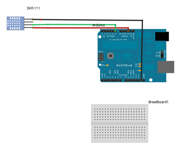
Now when I bought my DHT11 from Ebay, a picture like this was on the listing. Quite frankly, I don't understand what this is getting at. It doesn't work. While I can't vouch for the rest of the world, my sensor is not analog. It is digital. You can even look at the datasheet.

Correct Wiring:
Pin 1: +5V
Pin 2: Signal. Connect to digital IO with a 5k ohm pull-up resistor
Pin 3: Nothing. Some people suggest grounding it if you run into trouble
Pin 4: GND


Once everything is wired up, open the example sketch. It does about everything I would want it to do, so there is not much to say. Uncomment the correct sensor and upload. Open the serial monitor and get testing. 

There isn't much to say about this sensor. It is slow and probably not too accurate, but with the hard work of making the library already done, this sensor is incredibly easy to use. If you don't like my description of this sensor, there are many others out there at your disposal. If you do like it, I'm glad I could be of help.

-Matthew

Saturday, November 16, 2013

iRobot Create: Arduino Control

Introduction

This is the fourth section of the iRobot Create tutorial. If you have not completed the first sections, I would recommend that you go back and do so by following the links below.

Sections

Reference Documents

These documents should be referenced for details on interfacing with the Create
  • iRobot Create Open Interface Manual (OIM)- This manual provides detailed information on the serial interface with the Create. It details the implementation of the opcode system used to control the various systems as well as the necessary measures that must be taken to receive sensor data from the Create. Information regarding sensor packet size, connector pinouts, and command details can be found here.
  • Roomba Class Reference Guide (CRG)- This document provides support for the Arduino "Roomba" library. Here details can be found regarding the functions included in that library.
  • iRobot Create User Manual - This manual provides an introduction to the basic functions of the Create and an overview of the basic onboard functionality

Necessary Hardware

Necessary Software


Arduino Control

Arduino control can be implemented using the Roomba library. This library handles all the background serial commands allowing the user to program the Create's functions using the Arduino IDE. If the Roomba library is not installed download it HERE. Unzip and install the library then restart the Arduino IDE (See How to Install a Library).

Arduino Basics

This tutorial assumes basic knowledge of the Arduino IDE. If instructions are unclear or problems arise concerning the Arduino system, refer to THIS page and my previous posts (the ones labeled Arduino).


Wiring

Connecting the Arduino Mega to the Create is simple. In general, connections should be made according to the chart below. See my post, iRobot Create - Arduino interface cable.
Note that Serial1(TX1/RX1) should be used on the Arduino Mega. The serial port output TXD from the Roomba/Create is too weak to drive the RX serial port (Serial0) input of an Arduino properly. This is because of the USB-Serial converter on the Arduino: it also tries to drive the RX serial port input via a pullup resistor, but the Roomba does not have enough drive to pull the RX down below about 2.5 volts, which is insufficient to be reliably detected as a TTL serial input of 0. Furthermore, using Serial1 still allows for the use of the Arduino Serial Monitor for debugging purposes. Also note that Serial2 or Serial3 could be used if selected in software.
Arduino Mega PinCreate Cargo Bay Pin
TX1 (pin 18)RXD (pin 1)
RX1 (pin 19)TXD (pin 2)
GNDGND (pin 14)
Cargo Bay Pinout.JPG
ArduinoMega pinout.png

In this tutorial, connections will be simplified using a custom interface shield and ribbon cable. Connect the Arduino as shown below. See THIS post for details on the custom interface shield and cable.
IRobot Create Arduino Wiring 1.jpgIRobot Create Arduino Wiring 2.JPG
Note:
  • The direction of the ribbon cable is important. It must be connected as shown.
  • The connection of the TX/RX cable is important. Connect it exactly as shown.
    • White: TX1 pin 18
    • Black: RX1 pin 19
  • When using the cargo bay connector, ensure that the mini-DIN connector (the one used with the Create serial cable) is unplugged.

The recommended input voltage for an Arduino is 7-12V, center positive. Verify battery voltage before connecting. 


Checking Connections: TestSuite

This example is included in the Roomba library (see "Necessary Software"). It allows for a quick assessment of Arduino-Create communication.
1) Open TestSuite.pde - In the Arduino IDE: File > Examples > Roomba > TestSuite
2) Connect the USB cable to the Arduino. Install the driver if not already done (How to Install Arduino Drivers)
3) Upload Program
  • Tools > Board > Arduino Mega 2560
  • Tools > Serial Port > [COM port]
  • File > Upload 
4) Open Serial Monitor - Set baud to 9600
5) Restart Arduino Mega by pressing restart button

A message indicating 0 errors should be displayed in the Serial Monitor and the Create should play an audible melody. If errors are reported, check the items listed below. Proceeding to other examples will be futile until these errors are eliminated.
  • TX/RX cable: White -> pin 18 , Black -> pin 19
  • Orientation of ribbon cable
  • Serial monitor baud rate
  • Arduino Driver Installed
  • Correct COM port selected

Controlling Drive Output

This example shows the basics of controlling the Create's movements. There are 2 basic functions that can be used to control the Create's drive motors. The Roomba library provides support for both. Details regarding usage of the 2 functions can be found in the Roomba Class Reference Guide. Information on maximums, minimums, and special cases can be found in the Open Interface Manual. 
  • drive(int16_t velocity, int16_t radius) - Velocity is in mm/s. Radius is in mm. Special values can be found in the CRG.
  • driveDirect(int16_t leftVelocity, int16_t rightVelocity) - Velocity is in mm/s.

1) Turn Create to OFF.
2) Open Roomba_Drive_Test.ino - In the Arduino IDE: File > Examples > Roomba > TTU Examples > Roomba_Drive_Test.ino or copy sketch from link at the bottom of the section.
3) Upload it to the Arduino Mega.
WARNING: If the Create is on, the sketch will start as soon as the upload is complete. Before uploading, turn the Create off. It is important to note that the Create may be ON even if the power LED is off. The power LED turns off when the Create is put in safe or full mode as well. Cycling power until the power LED is lit and then goes off will ensure that the Create is truly OFF. Regardless, it is a good practice to ensure that adequate space is available in case of accidental movement.
4) Disconnect USB and connect Arduino external power.
5) Place Create on large, flat surface (ie. the floor)
6) Power up the Create.
7) Restart Arduino.
The Create should cycle through a series of movements using the two methods of control as defined below. 
  • driveDirect
    • Drive straight
    • Spin CounterClockwise
    • Spin Clockwise
    • Stop
  • drive
    • Turn Left
    • Turn Right
    • Drive Straight
    • Spin Clockwise
    • Spin CounterClockwise
    • Stop


Reading Sensor Data

Sensor data can be read in two different ways. While both methods are described in the OIM, this example will only cover the getSensors() approach. The Create automatically updates its sensor data every 15ms. The user can choose often to read the values of those readings. While calling getSensors more frequently will cause no harm, the values read in that period will be redundant.
To read a sensor, the following information is needed
  • Sensor packet ID - the number associated with the sensor value the user is trying to read. Packets 0-6 are associated with groups of sensor values. Packet 6 is associated with all sensor values available 
  • Size of sensor packet (in bytes) - the number of bytes returned when the user calls a sensor packet ID 
  • Variable type returned - the way the bytes received must be interpreted. 
Example 1: Packet 7 returns one byte. However, it must be interpreted as individual bits. A value of 3 means that bytes 0 and 1 are 1s and therefore the Left and Right Bumpers are triggered.
Example 2: Packet 28 returns 2 bytes. They must be interpreted as one unsigned integer value. As in the "Drive Forward 20cm" example, a value of 1 and 44 would mean that the Left Cliff Sensor is reading 300.
All of this information can be found in the Open Interface Manual beginning on pg. 17. 
Useful Arduino functions for interpreting sensor values
  • bitRead - Reads an individual bit in a byte
  • Bitshift - Shifts the bits in a variable in either direction. Useful for high_byte, low_byte composition
  • BitShiftCombine - Function included in the example (defined at the bottom). Uses Bitshift to combine to bytes into a 16 bit int. Note that the int may be signed or unsigned depending on the receiving variable type. 

getSensors(uint8_t packetID, uint8_t* destination, uint8_t length)
  • packetID - number of packet to read
  • destination - an array with at at least "length" entries. Note that arrays are 0-indexed. ie, the first value in an array of 52 entries is array[0]. The last entry is array[51].
  • length - number of bytes associated with packetID being used.

Process for running sketch:
1) Open Full_Sensor_Test.ino - In the Arduino IDE: File > Examples > Roomba > TTU Examples > Full_Sensor_Test
2) Upload sketch to Arduino Mega
3) Open Arduino Serial Monitor - Set baud to 57600
4) Power ON Create
5) Restart the Arduino
Data from sensor packet 6 (all sensor data) should be displayed in the Serial Monitor. For more information regarding the nature of the sensor data, see the Open Interface Manual.


Basic Object Avoidance

This example demonstrates the use of the Create's sensors to navigate around obstacles. When executed, the Create should drive forward. When it bumps into an object, it should back up and turn away from the object. Sensor data is read using getSensors and motor control is implemented using driveDirect.


1) Turn Create to OFF.
2) Open Basic_Object_Avoidance.ino - In the Arduino IDE: File > Examples > Roomba > TTU Examples > Basic_Object_Avoidance
3) Upload sketch to the Arduino Mega.
WARNING: If the Create is on, the sketch will start as soon as the upload is complete. Before uploading, turn the Create off. It is a good practice to ensure that adequate space is available in case of accidental movement.
4) Disconnect USB and connect Arduino external power.
5) Place Create on large, flat surface (ie. the floor).
6) Power up the Create.
7) Restart Arduino. 

iRobot Create: MATLAB Control

Introduction

This is the third section of the iRobot Create tutorial. If you have not completed the first and second sections, I would recommend that you go back and do so by following the links below. They provide more insight into how the toolbox actually works. This section covers control of the iRobot Create via MATLAB. If you do not have access to MATLAB, feel free to skip this section. While it may be possible to use GNU Octave (a free Matlab compatible software), I know very little about that(Update: See my post on Octave serial communication HERE. More details on an Octave package coming soon).

Sections

Reference Documents

These documents should be referenced for details on interfacing with the Create
  • MATLAB Toolbox Documentation - This document provides details on the various functions included in the MATLAB toolbox. More information can be found in comments in the functions themselves.
  • iRobot Create Open Interface Manual (OIM)- This manual provides detailed information on the serial interface with the Create. It details the implementation of the opcode system used to control the various systems as well as the necessary measures that must be taken to receive sensor data from the Create. Information regarding sensor packet size, connector pinouts, and command details can be found here.
  • iRobot Create User Manual - This manual provides an introduction to the basic functions of the Create and an overview of the basic onboard functionality

    Necessary Hardware

    Necessary Software


    MATLAB Control

    Another convenient way to control the Create is with a MATLAB toolbox. The MATLAB toolbox to be used in this lab (Developed by Joel Esposito at the US Naval Academy) allows the user to control the Create from any computer via a serial tether. This lab will explore the basic functions of this toolbox. See comments in the scripts for details on each function. For more information, see comments in the functions themselves or read the MTIC Documentation

    Before beginning, download the MATLAB toolbox HERE and unzip it into the folder in your MATLAB directory. In windows it will be "C:\Program Files\MATLAB." Next connect to the computer the Create using either the iRobot serial cable and a serial extension or a bluetooth serial link. Open the Device Manager and make note of the COM port associated with the Create. Open MATLAB and proceed.

    ExampleButtonBeep

    This example demonstrates the use of the Create's Advance and Play buttons. When in Full or Safe Mode, these buttons may be read as digital inputs. The function ButtonSensorRoomba returns 1 for a depressed button and 0 for a button that is not depressed.
    1) Open ExampleButtonBeep.m
    2) Set serial port to COM port associated with Create. 
    Example: For a Create connected to COM 8. Change RoombaInit() to RoombaInit(8) 
    3) Click the green run icon in the center of the MATLAB toolbar.
    4) Press combinations of the Play and Advance buttons to hear different patterns of beeps

    ExampleDrive

    This example explores two of the ways the user can control the Create's wheels, SetFwdVelRadiusRoomba and SetDriveWheelsCreate. See comments in the scripts for details on each function. For more information, see comments in the functions themselves or read the MTIC Documentation.
    1) Open ExampleDrive.m
    2) Set serial port to COM port associated with Create. 
    Example: For a Create connected to COM 8. Change RoombaInit() to RoombaInit(8) 
    3) Place Create on large, flat surface (e.g. the floor).
    4) If not already done, turn Create to ON.
    5) Click the green run icon in the center of the MATLAB toolbar. 

    Observe how each function moves the Create. Note the distance measurements displayed in the MATLAB Command Window. They are the distance readings from the Create's wheel encoders. Note that the distance is taken as the average of the two wheels, so if one wheel traveled 1m and the other wheel traveled -1m. The distance is still 0. 

    Explore how different inputs effect the Create's movements and the sensor readings.

    ExampleDrive2

    This example demonstrates two of the ways to control the Create's wheels using feedback from the Create's wheel encoders, travelDist and turnAngle.
    Note: travelDist and turnAngle use scripting from the Create Open Interface. This means that these functions are blocking. The Create waits and will not accept any new commands (e.g. requests for sensor data or commands to STOP!!) until it has traveled the desired distance. For this reason, use of these functions should be limited to small distances.

    1) Open ExampleDrive2.m
    2) Set serial port to COM port associated with Create. 
    Example: For a Create connected to COM 8. Change RoombaInit() to RoombaInit(8) 
    3) Place Create on large, flat surface (e.g. the floor).
    4) If not already done, turn Create to ON.
    5) Click the green run icon in the center of the MATLAB toolbar. 
    Observe how each function moves the Create.
    Explore how different inputs effect the Create's movements.

    ExampleSensorRead

    This example demonstrates the various methods of reading the Create's sensors. For details on interpreting the sensor readings, see the Create Open Interface Manual. 
    Note that not all sensor read functions are included in this example. See the MTIC documentation for information on other individual sensor read functions. 
    1) Open ExampleSensorRead.m
    2) Set serial port to COM port associated with Create. 
    Example: For a Create connected to COM 8. Change RoombaInit() to RoombaInit(8) 
    3) If not already done, turn Create to ON.
    4) Click the green run icon in the center of the MATLAB toolbar. 
    Observe the values printed to the MATLAB Command Window from the different functions. Note the format of each reading. Using the Create Open Interface Manual and the MTIC documentation, interpret each value displayed and consider how that value might be useful. For example:
    CliffRgt = 0. What does that mean?
    Wall = 1. What does that mean?
    pCharge = 66.4563. What does that mean? 

    ExampleBasicObjectAvoidance

    This example demonstrates the implementation of basic object avoidance using the Create's bump sensors. 
    The Create drives forward until it encounters an object and turns away from it. Pressing either button (Advance or Play) while the script is running stops the Create. 
    Note: Set Serial Port to port connected to Create
    Note: ctrl + c stops execution of MATLAB code 
    1) Open ExampleBasicObjectAvoidance.m
    2) Set serial port to COM port associated with Create. 
    Example: For a Create connected to COM 8. Change RoombaInit() to RoombaInit(8) 
    3) Place Create on large, flat surface (e.g. the floor).
    4) If not already done, turn Create to ON.
    Note: To stop the Create's movements, press one of its buttons or simply lift one of its wheels off the ground. If the Create becomes disconnected from the computer, it will follow the last command it was given.
    5) Click the green run icon in the center of the MATLAB toolbar. 
    Observe the behavior of the Create. Make changes to the example sketch to improve its functionality. What do the limitations seem to be in the system?

    ExampleKeyboardControl

    This example demonstrates keyboard control of the iRobot Create. 
    Note: Exiting keyboard control by any method other than pressing 'q' (e.g. clicking the red x on the window) will likely crash MATLAB. 
    1) Open ExampleKeyboardControl.m
    2) Set serial port to COM port associated with Create. 
    Example: For a Create connected to COM 8. Change RobotHardKeyBoard() to RobotHardKeyBoard(8), and change RoombaInit() to RoombaInit(8) 
    3) Place Create on large, flat surface (e.g. the floor).
    4) If not already done, turn Create to ON.
    5) Click the green run icon in the center of the MATLAB toolbar.
    6) Use keyboard commands displayed on screen to control Create.
    7) Press 'q' to end keyboard control

    Friday, July 19, 2013

    Whirly-Gig: Charlieplexing and SoftwareServo on ATtiny45

    I recently completed a project involving an ATtiny45 and wanted to share it with the world. The idea came from the world of FIRST robotics. At competitions some teams have spinning banners ("whirly-gigs") above their pits to attract scouters, judges, and anyone else who might be interested. I had a friend who saw it and told me to make one for her birthday. Sounds like fun! Let's get started.

    Hardware involved:

    • 1: ATtiny45
    • 1: HXT900 Servo (modified)
    • 1: Momentary Switch
    • 1: 10k Potentiometer
    • 1: 5V Voltage Regulator
    • 1: DC Power Jack
    • 1: 2 Way Switch
    • 1: 3 Battery AA Holder
    • 6: 5mm Colored LEDs
    • 3: 270 Ohm resistors
    • Wire
    Software Involved
    First, the ATtiny core. I have done several posts involving ATtinys in the past. Follow the instructions from the link above to use an ATtiny with the Arduino IDE.

    Second, the SoftwareServo Library on the ATtiny. I have already done a post on controlling servos with an ATtiny. Find it HERE. Basically, the regular Servo library will not work because it doesn't have the necessary timer, so SoftwareServo must be used.

    Next we have the Charlieplex Library. It takes care of setting the pins correctly to turn on the LEDs we will be using. I have done a post on this library as well. Find it HERE.

    Last we come to my sketch. You can get it HERE. It may be a bit convoluted , so I tried to comment it to be understandable. The essence is this, there are 10 different LED modes that the user switches between by pushing a button. At the same time the servo which has been modified for continuous rotation as discussed HERE is controlled by turning a 10k pot.

    I made a nice wooden base for the electronics and mounted the servo on 2 wooden uprights. The sign itself is made of dowel rods and home insulation foam cut into circles. I made it such that an 8.5 x 11 sheet of paper will fit on it when rolled horizontally.

    I soldered together all the electronics. I put a 270 Ohm resistor on each LED pin. I also put a 10 uF electrolytic capacitor across the power leads and a diode protecting against unwary users plugging in power backwards, but those probably aren't necessary.

    I did run into one problem in the course of this process. The servo would stop working when I set a certain LED pin LOW. I never did get to the bottom of it, but it is discussed in THIS forum thread. I ended up changing the pins I was using, and it solved the problem. I included a diagram of my pinout in the code posted above.

    That's about all the details I am going to give you. The whole project took quite a while, and it's a DIY project. I'm not selling kits. If you want, you can view my project photos HERE, and I took a nice video for you to look at. I hope I inspired you to greatness.


    -Matthew

    Saturday, July 13, 2013

    Charlieplexing on an ATtiny85: 3 pins, 6 LEDs

    While exploring the world of ATtinys and Arduinos I came to a problem. I needed to control 4 LEDs with only 3 pins. Well this is a problem. I scurried around trying to conceive a clever way to borrow a pin from another application to no avail.

    Having previously encountered multiplexing, I turned to that. There I found my solution. Charlieplexing. According to Wikipedia, Charlieplexing uses the tri-state logic capabilities of microcontrollers to control gobs of LEDs with a few pins. The details of Charlieplexing are a bit confusing. I don't feel fully qualified to explain them, so here are the important things to know.

    1) An Arduino pin can be in 3 modes: OUTPUT: HIGH, OUTPUT: LOW, or INPUT. When a pin is set as an input, it is put in a high-impedance state. Outputs are in a low-impedance state. If you have no idea what I'm talking about, see THIS link.

    2) LEDs (Light Emitting Diodes) only work in one direction. If you did not know this you may have at some
    point wondered why your LED was not working. Don't worry. Ignorance isn't a crime...that I know of.

    3) Your Arduino (even your ATtiny) can turn LEDs on and off many more times a second than your eye can see. Think how a video shot at 30 frames per second (NTSC TV) looks. That's 30 Hz. A "normal" Arduino runs at 16 MHz (16000000 Hz). Now granted you can't turn an LED on and off that fast, but you get my point. I will be running the ATtiny at 8MHz. This is the fastest you can run it without external hardware.

    All this combined means that I can control 6 LEDs with only 3 pins. Great! Next I searched for a library to take care of all the heavy lifting. Introducing the Charlieplex Library. This library takes care of all the tedious stuff to let us worry about what we want the LEDs to do at the Macro level.

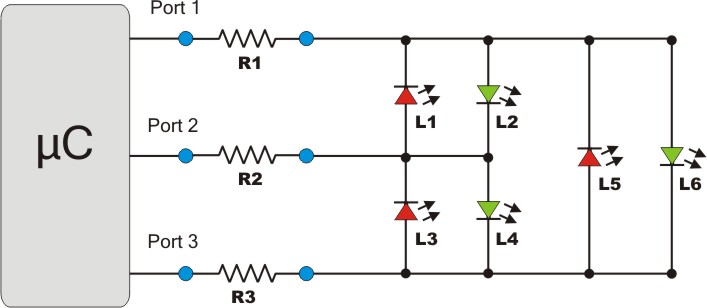
    I'm not going to go into the details of how to use the library because the Arduino playground page does a pretty good job. However, for those that are interested HERE is my code. It is a basic modification of the SimpleCharlie example to control 6 LEDs.

    To the right is a schematic for how to wire up the LEDs. There are also resources available on Google to help you do that. HERE is one resource on how to draw your own schematic. Video would be rather anticlimactic, and I have already disassembled it. The schematic will have to do.


    Hope this works for you. 
    -Matthew

    Thursday, June 13, 2013

    Serial Communication on a ATtiny85 with the SoftwareSerial Library.

    "Serial is giving me errors on my ATtiny! What can I do?" We have a solution.

    Serial communication is not difficult on an ATtiny thanks to the SoftwareSerial Library. While the ATtiny85 does not have the hardware of a "real" Arduino, it can still function in similar fashion. If you're just getting started with using an ATtiny, here are some resources you might need.

    • Information on programming them from High-Low Tech. You can also look back at my previous posts.
    • My nifty programming adapter. A few minutes of soldering made my life much easier.
    • My USBtinyISP is discussed in THIS post. It also makes life easier.
    • Previous posts on Running Servos and the NewPing Library on an ATtiny.
    • THIS previous post mentioning my USB to UART converter cable
    Now we are ready to go. First things first, I am using Arduino 1.0.4. The SoftwareSerial Library is included as a default library, so there is no reason to get a 3rd party library.


    Step One: Wire it up. With my USB to UART cable it is as follows.
    • Black: Ground
    • Green: Tx (using Tx as pin 4)
    • White: Rx (using Rx as pin 3)
    • Red: 5v (this is optional if you have an external power supply)
    Connect an LED with appropriate resistor to pin 1.

    Step Two: Ensure that your ATtiny is burned to run at 8MHz. Now load THIS sketch onto the ATtiny. Note that parseInt() works with the SoftwareSerial Library.

    Step Three: Open the Serial Monitor and set it to the correct Baud rate. To reset the ATtiny, bridge the reset pin to ground momentarily. When you see the connected message, enter an integer and count the flashes.

    That's all there is to it. I you don't have a USB UART cable, this is easily adaptable to communication with another Arduino with a USB port. See THIS post for code. If you want to see a practical application of serial communication on an ATtiny85, check out my serial sonar controller HERE.

    Hope this works for you all. As usual, if there are any questions, just let me know.
    -Matthew

    Tuesday, June 4, 2013

    Arduino RTC: TinyRTC v1 with Arduino Mega 2560

    This post is slightly out of sync with my previous ones. I was digging around in my parts box and found my real time clock (RTC) module, a TinyRTC v1. I then realized that I had not posted any of my findings when I used it. Well I had a few minutes today, so I decided to dust off the RTC and see if it was still working.

    A real time clock is something many new hobbyist might take for granted. Living in a world of computers with integrated RTCs and internet connections, it's easy to forget just what it takes to keep track of the time. While any Arduino can give you the time since it's last restart (or pretty close to it anyway). To keep track of the time displayed on your cuckoo clock you will need some external hardware and a continuous power supply. Various people have come up with  good combinations of said hardware, and all you need to do is buy a RTC module.

    The module I will be using is a Tiny RTC v1 module. They are commonly found on Ebay called "Real Time Clock DS1307 I2C AT24C32" or similar. Communication is done over an I2C interface. It has a battery on-board that can supposedly last for several years.

    I didn't really remember how I set up the RTC, so I started digging around. I found 2 sketches that I picked up from somewhere. I believe the Ebay seller posted them. I tried them out, and they do work as expected. SetRTC sets the RTC with a time you hardcode into the sketch. GetRTC simply displays the time given from the RTC. Both sketches require the Wire library and the I2C address. To find the I2C address, use THIS I2C scanner.

    First wire it up. Connect SCL and SDA to the appropriate pins (21 and 20 on the Arduino Mega 2560). Connect Vcc to 5v and GND to GND. Ignore the rest of the pins. To the right is a diagram of the connections for an Uno if you are confused. Next set the time in the function and upload SetRTC to your Arduino. Then hit the reset button at the moment you want to set the clock.

    Now we can upload the GetRTC. Open the Serial Monitor and watch the seconds tick by. An interesting note, if you unplug the GND and reattach it, the time gets corrupted, and you will have to reset the time.

    Now, while this method works, I would be remiss if did not mention the Time library. It has many other functions that may be useful depending on your situation. I have not explored them, but I assume it works well. To set the time using the library you will need to download Processing. By using a Processing sketch, you can sync the clock's time to that of your computer.

    That's all for today. Go forth and make data loggers, binary clocks, and other exciting projects.
    -Matthew

    Thursday, May 30, 2013

    Stepper Motors and Arduino: 28BYJ-48 with ULN2003

    Today I will be exploring the world of stepper motors. I recently purchased a 28BYJ-48 stepper motor with a ULN2003 controller. They are available from a host of vendors for a few dollars and seem to be pretty popular in the Arduino community.

    Getting started, there are several links you might find useful.

    • Basic information on the motor and controller as well as a sample sketch using the standard Stepper library.
    • The Stepper Library- This is the library that is included with the Arduino IDE. This library is set up to run a stepper without a gearbox, so it would have to be modified.
    • Stepper2.ino- This sketch includes a full set of functions that can be used to run the 28BYJ-48. It is discussed on THIS page, but it appears that the plans to convert it into a "real" library were never implemented. 
    • Custom Stepper Library- This library can be used to control a variety of steppers, but the default settings are for the 28BYJ-48
    First I just wanted to get the stepper turning. I found THIS forum thread with some basic code to get it running. HERE is the code. It is very basic and does work. If you read THESE notes and still didn't understand how steppers work. This sketch might clear it up for you. Below is a video of the sketch working. 

    Note how it is wired. You don't want to power the stepper from the Arduino. It can pull 90mA which is a lot for your little Arduino. I used my nifty breadboard power supply that I picked up for a few dollars on Ebay. Power goes to the left 2 male pins on the ULN2003 breakout (marked - + 5-12V). The jumper on the right just switches power to the motor. Removing it opens the circuit between the + power supply and the motor. Other than that, just use some female-female jumpers to connect the inputs to the whatever pins you are using on the Arduino. I am using an Arduino Mega 2560 with an Arduino sensor shield v4, so this is very easy to do. For those that don't know, the ULN2003 is just a little Darlington Array that allows us to switch power from an external source on and off rather than using the Arduino's on board power supply.

    Next I decided that I would try the Arduino Stepper library first. While Stepper2 looks promising, I wanted something actively supported. Luckily THIS wiki provides code for using the standard library. HERE it is again, saved for posterity. I will note that 4096 steps resulted in 2 revolutions. Also, at the default steps/revolution 300 appeared to be a good maximum speed. 400 would not run at all. When I changed the steps/revolution to 2048, 10 worked well as a max. Another useful thing to know, the clockwise and counter-clockwise directions are defined when looking at the motor from the back (the side with the label). That is, from the perspective I used in the video above it will be backwards. 

    If it is not working try some of the things below. If those don't help, Google the problem. If all else fails, comment, and I will see what I can do.
    • Reduce the speed. These motors only turn so fast before they bind up and stop moving.
    • Check the motor's temperature. The top speed of mine seemed to depend a bit on how warm it was.
    • Check wiring. Make sure your Arduino is hooked up correctly and you have defined the right pins in your code.
    • Check the jumper on the ULN2003 control board. It must be in place (bridging the right two pins).
    Well that's about all I have at the moment. I have not dug into the other two stepper libraries I listed. I just wanted to do an intro so I could add stepper motors to my robo-arsenal. If I do any projects with them I will post about it.

    -Matthew

    Tuesday, May 28, 2013

    nRF24L01+ Arduino Communication on Arduino Mega 2560

    Disclaimer: Note the last paragraph.

    In my quest to explore inter-Arduino communications, I bought 2 nRF24L01+ modules. These are pretty neat radios. From what I have read, they are AM. They can be used with key fob remotes or in a network of up to 6 modules. They are also very cheap. My 2 were $3 on Ebay, but many vendors sell them.

    When I first began working with these modules I needed a way to interface with them. Wanting to
    breadboard at least one of them, I created the adapter shown to the right. It isn't a perfect solution. The module itself gets in the way of wiring slightly, but my jumpers fit in there good enough.

    Next I loaded the RF24 Library. HERE is a blog post by maniacbug that details using the module on an Arduino Uno. It is very useful. THIS page also helped. However, I don't have an Uno. I only have an Arduino Mega 2560. This means that we need to change a few things.

    First, we need to change the pins. The Arduino Mega's SPI pins are in different positions than the Arduino Uno. You can figure these out pretty well or you can look below.
              Uno           Mega

    • 11       -      51            (MOSI)
    • 12       -      50            (MISO)
    • 13       -      52            (SCK)
    • 10       -      53            (CSN)
    • 9         -      40 (Your choice) (CE)
    Another note, IRQ is not needed for anything I will be discussing. Just leave it unplugged. 

    Second, the code needs to be changed slightly.
    RF24 radio(9,10);        needs to be changed to      RF24 radio (40, 53);

    On the receiving end, I decided to use my Hackduino. Since it is basically an Arduino Uno, the pins are wired the same, and the example code does not need to be changed at all.

    However, I did have the problem of needing a 3.3V power supply. Well a few minutes and a Google search later I found THIS calculator and built my first voltage divider circuit. I used a 470 Ohm resistor between 5v and output. 220 and 22 Ohm resistors in series (for a total of 242 Ohms) were placed between output and ground. I read it with a volt meter and it was right on the money, 3v3.
    3.3v voltage divider
    Black: GND   White: 5v    Green: 3.3v output

    Well here goes nothing. Open the serial monitor and type t. I got this screen.

    The first part of that is fine. The second is not.

    Well I did some digging. While I had found two forum threads (HERE and HERE), I had not found them terribly useful. They came to the conclusion that he Arduino Mega power supply was the problem. While this may be the case, no combination of capadcitors seemed to fix it. I also went on to try the power supply from my Hackduino, 2 AA batteries, and the 3.3V supply on my breadboard power supply. None of these things worked.

    I did successfully get it to send once, but I have no idea how. It just worked. I unplugged the USB and plugged it back in, and it didn't work. I have rung out every jumper I am using and have tested all the pins with an LED. I swapped my two RF modules out. Same problems. At this point, I really have no clue what the problem is. I don't have an Arduino other than this one to try it on. I also don't have a variable power supply to test with.

    Well that's all I have. I admit that I am quite disappointed with myself for posting an unsuccessful project. I don't know if I will continue working on it or not, but if I do get it working I will post an update. I may try the Mirf library, but we will see. I only paid a few dollars for these modules, and if they are bad I don't want to waste any more time on it. If anyone has any suggestions, feel free to comment. Regardless of my apparent failure, I still learned quite a bit in this endeavor. I hope you have better luck!

    -Matthew

    Monday, May 13, 2013

    Arduino: I2C Communication between 2 Arduinos with Wire Library

    The next method of communication I will look at is I2C communication. I2C stands for Inter-integrated circuit. It allows one master device to connect to a large number of slave devices using only 2 pins (signal and clock).  The nice folks at Arduino have made this very easy with the Wire library. It is included with the Arduino IDE and is supported on most Arduino boards.

    Before we begin you may want to peruse the Arduino website. The Wire library is described HERE and detailed HERE.  When you finish those, let's dive in.

    The first thing I did was run the master_reader and slave_sender examples. This was very easy. It sends hello from the slave to the master and displays it on the serial monitor.

    Below is a picture of the wiring. It is simple. Wire the SCL pins and the SDA pins together through a pull-up resistor. I used 4k7. A good example can be found at THIS instructable. You also need to connect the grounds of the two boards as well as the vcc. I copied over the diagram for convenience (to the right).

    Next I decided to make it transmit something useful. I made an I2C HC-SR04. The slave Arduino constantly takes distance measurements with the HC-SR04 sonar module. The master Arduino can then poll the slave whenever it wants to get the current distance measurement.

    Wiring is the same as above. Make sure you use your pull-up resistors. I connected the trigger pin of the sonar to pin 7 and the echo to pin 8, but you could use any of them.


    HERE is my code. Hopefully I will have time to rewrite the slave for the ATtiny in the future. That is the plan. Right after wireless communication, robot arm, computer vision..

    Matthew