Showing posts with label USBtinyISP. Show all posts

Sunday, April 28, 2013

Using Reset pin as IO on ATtiny85/45 with avrdude and USBtinyISP

Today I'm going to discuss my successful attempt to use the reset pin of my ATtiny45 as an IO and then change it back again. I'm not going to go into a lot of detail because, a) I'm not an expert and b) other people already have. I'll just provide links to the useful pages.

The theory behind this is pretty simple. Basically, you change some fuse bits and the reset pin becomes pin 5. Unfortunately, this means you can't program it with a ICSP (like the USBtinyISP) anymore. You need a High Voltage Serial Programmer that supplies 12v to the reset pin before changing the fuse bits. There are several Arduino forum threads on this out there. Chances are you found those before you found this blog. Now lets get started.

1. You need to get some software. Follow the instructions from Ladyada to install WinAVR

2. You need load a test sketch into your ATtiny with your USBtinyISP or other programmer. I'm assuming you know how to do this. If not go HERE. I used blink with the pin changed to pin 5. If you load it and wire up the LED you shouldn't get any light.

3. Now you need to enable the reset pin as an IO (and thus lose programming capability). This is slightly involved. I recommend you see more instructions from Ladyada. They are very in depth and useful. If you want bare bones you can look below.
  1. Find a fuse calculator. I used THIS one. Select the options you want. I used default with reset disabled. Copy the AVRDUDE arguments.
  2. Open a command window by searching for cmd in the start menu.
  3. Type the commands to set the fuses: avrdude -c [insertyourprogrammerhere] -p [enteryourboardhere] -U [enter the arguments you previously copied here].  Example: If you are using an ATtiny45 and a USBtinyISP like I am (and are extremely lazy), copy and paste this line into the command window:     avrdude -c usbtiny -p attiny45 -U lfuse:w:0x62:m -U hfuse:w:0x5f:m -U efuse:w:0xff:m
  4. Watch and wait. You should get a nice thank you message. You're done.
You're reset pin should be acting like an IO now. If you plug in your LED now, it should blink nicely.

That's great! You know have 6 IO pins at your disposal, but you want to load a new program onto the chip. You need a HVSP. Go forth and Google search. To save you some time here are the cheap options out there.
My Arduino resetter circuit. 
I ended up using the last one, and it does work. All you need is a breadboard, jumpers, 6- 1k resistors, a 2N3904 NPN transistor (I found one on an old cordless phone), and an Arduino. You'll also need some source of 12V. Anyway, you pretty much just follow the instructions on the webpage above. After I discovered the bad jumper I was using, it went smoothly. 


When you finish, the LED on the reset pin should no longer work, but you will be able to program the chip again. This is good. You have successfully reset the fuses.

That's about all I have for this post. I hope you found it useful. Be sure to check out those other websites. They have a lot of good information.

-Matthew
Here's another picture.

Monday, April 8, 2013

Upload sketch to Arduino Mega with External Programmer

Well I just "wasted" 30 minutes of my life and thought I should share it with the world.

As I have previously mentioned, I have an Arduino Mega with what I believe is a burnt out usb to serial chip. I haven't looked seriously into fixing it, but that might be a project for the future.

Anyway, as I now have a USBtinyISP, I thought I would try to program it with that.

Attempt One:  I found THIS webpage. Apparently you can change the setting in the preferences.txt to always upload via an external programmer. Well that's no good.  I only want to do it with one board. Oh wait,

"If you would rather use an external programmer for only an individual board, you can edit the boards.txt file in the hardware/ sub-directory of the Arduino application directory. Set the board.upload.using parameter to the identifier of one of the programmers in programmers.txt."

Well there's the solution. I'll create a new board that is just a copy of the Mega2560 except with the new settings.

Attempt Two: I found the Mega 2560 part in the boards.txt and go to deciphering. This goes rather slowly until I find THIS. Then I quickly sort it out into the correct lines and change what I believe needs to be changed. 

Upload. Error. Big surprise. 

I change some more settings and reopen the IDE. I go to open the blink example and notice something.

Attempt Three: "Upload Using Programmer". There it sits write below the upload command under the file tab. It works.

I abandoned my attempts to create the edited board file. It would just be redundant now. I don't know how long that option has been there. I checked, and it is there in the oldest IDE version I have (1.0.1). So it has been there at least since last October.

There is a moral to this story. Don't assume that because Google doesn't yield an easy solution, it doesn't exist. You may have just been skimming over it in the IDE.

May you always see the obvious.
-Matthew

Thursday, April 4, 2013

ATtiny85 programming adapter

I've been playing with the my ATtiny85 and have been enjoying it. However, programming it can be a pain, because I have to break out the jumper wires and the datasheet to figure out which wires go where. This got annoying quick, so I got to problem solving.

This was the result. It simply plugs into my breadboard on top of the ATtiny and then rearranges the pins into a convenient 6-pin connector for my USBtinyISP. It works pretty well. I wanted to make a full Arduino style breakout board for it but had two things inhibiting that.

This stuff is junk.
One, my female headers haven't come in yet. They are in the mail, so maybe I will do that someday. Two, the cheap perfboard that I bought is cheap. It only has contacts on one side. I struggled working with it for a while. When I pulled a pad off of one contact, I gave up and got the good stuff. I switched to the stuff from HobbyKing. Now on to making your own
.

What you'll need

  • Male headers- specifically you'll need 14 pins
  • Protoboard- I used THIS stuff and it worked great. Perfect size too.
  • Wire- I used some stuff I had around. I believe it is called Kynar.
Step One: Cut the board to length. I needed a grid that was 6 x 7. However, when I switched to the HK protoboard, it was close to the size, so I used that.

Step Two: Solder on the male headers that plug into the ATtiny. It is simplest to plug it into a breadboard while you do this so that you know it will be straight and fit in the sockets.


Step Three: Solder on the male headers that plug into the USBtinyISP. I did the same thing as above and just flipped it over and soldered it in the breadboard.


Step Four: Connect the dots. This takes a little ingenuity on your part. I put the side with the RESET and GND pins on the left so that most of the pins were fairly straghtfoward. Be sure to mark it so you know which way to plug in the cable. The important thing is that   they a) go to the right places b) don't go to the wrong places and c) don't go where the ATtiny will physically be when this thing sits on top of it.


Step Five: Ring it out. Now you go through EVERY pin on the thing and make sure it goes where its supposed to (see the above charts). Next you go through EVERY pin and make sure it doesn't short out anywhere or do anything else harmful. I will not be responsible for any fried chips but my own.


Not pressed down
Now go test it out. I found it quite a bit more convenient than breaking out the charts and jumper wires every time. It's also less prone to errors. I will mention that you may need to unplug other things when loading code. Example, I had a servo plugged into pin 1 and tried to load code. The servo jumped around and the code didn't load right. Also, it probably would not be good to hook it up when the chip is under power. I don't know that for a fact but call it intuition.

Here are some more pictures in case its fuzzy just how this thing is connecting to the ATtiny. It sits on top of it.
It place and ready to go.


Well that's all I have.  I hope you find this useful. Have fun in all your endeavors

 -Matthew

Monday, April 1, 2013

SoftwareServo library - ATtiny85/45/25

This post will cover the the examples of ATtiny that come with the modified SoftwareServo library found HERE Please note that the commands themselves have not been changed. I merely changed it for IDE 1.0+ compatibility and added a few examples. For information, check it out HERE.

What you will need:

  • ATtiny85/45/25
  • USBtinyISP or other method of programming
  • Hobby servo
  • Jumper wires
  • Breadboard
  • 10K potentiometer 
First, I am assuming that you know how to load programs onto the ATtiny. If not, please refer to my last few posts and THIS link.

Second, I'm going to assume you have either tried the Servo library that comes with the IDE and know it does not work or have read my previous post.

Third, don't expect the SerialServo example to work on the ATtiny.

Configure the ATtiny: We need it to run at 8MHz. Luckily it has an internal 8MHz clock. We merely need to plug it in, select ATtiny85 (internal 8 MHz) under boards and hit burn bootloader. It should load pretty quickly.

In case you don't want to read the datasheet. (credits)
Sweep: This is the first example I added. It is very similar to the sweep example from the Servo library. Notice that you have to refresh the servo manually. This could be useful or annoying depending on your situation. Regardless, it is the nature of the beast.

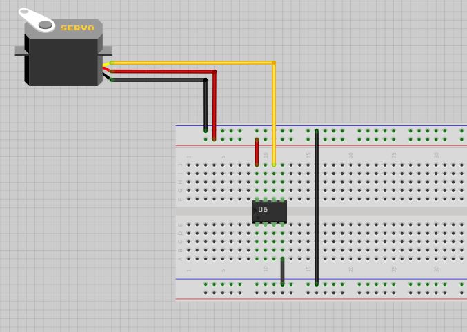
Here is a diagram of how you should wire everything up. It is pretty simple. As you can see from the pinout chart above, you could change the pins somewhat. 


Knob: This too is similar to the example found in the Servo library. This requires that you hook up a 10k pot to pin 3. As you can see, you can choose one of the other analog inputs instead if you wish. 

Again, here is a diagram of how you can wire everything up.


Now in case you are one of those people that just like to see the real thing, you can check out a video of sweep HERE and knob HERE.

If you have any questions or comments, either comment here or send me an email.
-Matthew


Friday, March 29, 2013

ATtiny85 Servo: SoftwareServo Library


Well I began work on my ATtiny85, and so far it has been quite the adventure. My initial thought was that it would be cool to use one on my differential steer robot, so I plunged into making this happen.
There are several problems with this that I have seen so far.
  1.  I will quickly run out of pins. I will probably want an ATtiny84. Maybe my 2313 will work. That’s another day.
  2.   The servo library will not work on the ATtiny85, reason being that the servo library relies on a 16 bit timer whereas the ATtiny only has an 8 bit timer.
  3.  The NewPing library does not work on the ATtiny. I believe this is the case anyway. The code will not compile. I haven’t looked into why this is. I’m assuming it has to do with the timers again. (Edit: check out my post on that HERE)
 Now I set out to solve all the problems of the world.

 Well I could just use an ATmega238 chip. All of the above problems solved, but that’s cheating.

Problem One: Like I said earlier, I will probably need to change hardware for this one. However, the ping sensors can be run on one wire for trigger and echo which I am not doing at the moment because my Arduino Mega had pins to spare. That would diminish the pin count by 2. I could also get my two bumpers on the front off of one analog pin by putting a different sized resistor on each one.

Problem Two: Now it gets fun. As it turns out, way back in the days of IDE 20ish there was a library called SoftwareServo library (more info HERE). All these young whippersnappers (Me) don’t know what that is because they got that newfangled timer based Servo library. Interesting. Well this can be used to our advantage. Long story short, download the library HERE. Stay tuned if you want to hear how I changed it.

 The changes are really quite elementary. All that had to be done was in SoftwareServo.h, change
            #include  <WProgram.h>       to      #include "Arduino.h"

This is to accommodate IDE 1.0+.  For those that might not know, you can use a variety of programs to do this. I used CodeBlocks because it was what was set was the default on my computer. You could probably manage with notepad on a change like this, but I’d go ahead and download a free compiler somewhere. Just Google C/C++ compilers. I’m really not experienced enough to recommend one.

Next I went to getting it running on the ATtiny. Well it was not as convenient to do so as some other libraries because it only came with one example, SerialServo. Well this is a problem because the serial library does not run on the ATtiny85 in its current form either, but that is a problem for another day.

I went typing away and eventually got it to work, so I added a few examples for lazy people like me. I already gave a link to it, but here it is again: SoftwareServo.

The rest is pretty simple. You do need to flash the ATtiny to run at 8MHz. That takes all of 15 seconds. Just connect it up, select the ATtiny85 (internal 8 MHz) option and hit burn bootloader. Details from High-LowTech.

It works really well. It’s perhaps a bit more jumpy than running on my Mega. That will happen though. I read an explanation on why that is, but it involves math and I really don't remember the details. I just know that the cut from a 16 bit timer to an 8 bit one cuts the resolution quite a bit.

Just for reference, there is also a Servo8bit library that I tried before I found the SoftwareServo library.I don’t believe it requires the Arduino IDE. I never got it to work, but maybe others can. Find details HERE. If you get it to work, let me know. I’d like to check it out.

That brings us to Problem Three. Well that is work for the future. I mainly just wanted to get a servo up and running. I succeeded with that. Yippee. Also, I got some new components and such. I will probably do a quick post on those soon too.

Happy Easter,
Matthew

Tuesday, March 26, 2013

Burn Bootloader to Arduino Mega 2560 rev3

This is quite a bit easier than updating the firmware on the ATmega16U2. Here's what I did.

Stuff you will need:

  • Your Arduino Mega
  • An USBtinyISP (mine says USBtinyISP v3.0)
  • Various software that I will mention
Step 1. Download the latest version of the Arduino IDE.

Step 2. Download and install the USBtinyISP driver found HERE.

Step 3. Download and install WinAVR, found HERE. Detailed instructions found HERE.

Step 4. Open the Arduino IDE. Select your board and the USBtinyISP programmer (do not select a COM port).

Step 5. Plug your USBtinyISP into the ICSP headers on your Arduino (the 6 male headers near the reset button). The red wire goes toward the pin 1 indicator mark. If like me, you had neither a red wire nor an indicator mark, see the *** section. 

Step 6. Plug the USB cable into the USBtinyISP. I left the jumper on it in place so the Arduino got power through the USBtinyISP. 

Step 7. Click Burn Bootloader and wait. It will take a few minutes.

***My USBtinyISP cable did not have a red wire so I had to do some snooping. First I got THIS diagram from HERE. Next I broke out the multi-meter and tested for continuity between the Arduino ground and 5V pins and the ICSP pins. Eventually I found them and worked out which way the cable plugged in. I then made an indicator mark on the Arduino and the cable in sharpie. The cable will only plug into the USBtinyISP one way on mine, but you could check that side with a volt meter too if you're worried about it. For me, the side of the connector that faced the USB socket on the USBtinyISP faced the USB socket on the Arduino.

As I mentioned previously, when I did this I got the error below, but the bootloader appeared to be burned anyway. If someone knows what happened feel free to fill me in. Hopefully it will work for you.

avrdude: verification error, first mismatch at byte 0x3e000
         0x0d != 0xff
avrdude: verification error; content mismatch

I'm not sure what I will write about next, but its sure to be exciting. Stay tuned.

Until Later,
Matthew