This is a quick set of instructions for installing ROS Kinetic on a Virtual Machine. This allows you to run ROS on Windows.
1) Install Virtual Box from this link.
2) Install the Virtual Box Extension Pack for your version of Virtual Box (also at this link). This allows you to use the USB ports on your computer within the virtual machine.
3) Download the Ubuntu 16.04 LTS .iso from this link.
4) Run Virtual Box and create a virtual machine with the .iso you downloaded.
5) In the virtual machine go to Devices > Insert Guest Additions CD image and install guest additions. This adds additional functionality, most notably the shared clipboard. Enable this under Devices > Shared Clipboad > Bidirectional.
6) Follow the instructions on the ROS Wiki to install ROS Kinetic (link).
7) Follow the instructions on the ROS Wiki to setup your Catkin workspace (link).
8) Make a snapshot of your new clean ROS install by going to Machine > Take Snapshot. This allows you to roll back to a fresh install if you tank it at some point.
9) Proceed to other projects! Here are some of mine to get you started (link)
Matthew
Showing posts with label Useful Things. Show all posts
Showing posts with label Useful Things. Show all posts
Thursday, September 21, 2017

Saturday, November 26, 2016
Arduino Interrupt Stepper Driver - CTC Mode
Introduction to the Problem
This tutorial will show how to drive a Pololu style stepper (A4988) driver using a timer interrupt. This method is non blocking, efficient, and as far as I know is pretty much what most 3D printer firmwares use.The idea is this. A pololu style stepper driver (the kind that plugs into the RAMPS board) only requires two inputs from the Arduino. One is a direction pin. The other is a pulse train. One rising edge equals one step (or micro step, depending on how the set pins are wired). Most people when they first get going with steppers probably do one of two things. 1) They use some library that does all this for them (I don't know if one exists, but maybe it does) or 2) They just throw a digitalWrite in the loop() and pulse it that way. The problem with that is that it is dependent on the speed with which the loop runs. Enter Timer Interrupts
Interrupts - Conceptually
The timer interrupt is a low level feature of the ATmega family. It is not something that is provided by Arduino, and in fact functions such as millis() and delay() are based on them. I have always been a bit surprised that Arduino does not break timer interrupts out a little. They are really pretty easy to use but are very powerful. I am not going to go into great detail on the specifics of timer interrupts because there are other sources out there. The best of which is the ATmega datasheet.The idea is this - the ATmega CPU is sitting there executing your code, pulling commands off of the stack. It does this in the same order each time. On another part of the chip there is this thing called a timer. It is counting up from 0 to some value over and over again incrementing at a set frequency. When it reaches the target value it sets a flag and goes back to 0. When that flag is set, the ATmega chip sees it and says, "it is time to execute a special piece of code. Drop everything and do it." What ever it was doing before goes back on the stack and what you put in the "interrupt service routine (ISR)" gets executed. Then it goes back to its normal business. We want to put our "pulse stepper driver" code in the ISR.
There are a couple of dangers with this, but I will just leave you with this. Keep the ISR short. Don't do any serial prints or heavy computations (floating point math) in there. Calculate those ahead of time and pull them in as compile time constants ideally.
Solving the Problem
Now I actually came up with 3 ways of solving this problem- Using a fixed rate Timer Interrupt and only pulsing on some of the ISRs
- Using CTC mode and pulsing inside the ISR
- Using a special PWM mode
This tutorial covers method 2. It uses Timer5 in Clear Timer on Compare (CTC) Mode. This allows you to call an interrupt at whatever frequency you want. If you're familiar with timer interrupts the picture below might help. Again, I will not take the time to go into that much detail on that in this post. For now, I will point you to the ATMega datasheet which covers all of this stuff and THIS post by maxembedded.
Another important point is that I use direct port manipulation in the interrupt. I will not cover that here, but there are numerous examples online of how that works in addition to the ATMega datasheet. HERE is one example. I use direct port manipulation because it is much faster. As stated above, the ISR should execute as quickly as possible.
 |
| CTC Mode - From ATMega Datasheet |
Another important point is that I use direct port manipulation in the interrupt. I will not cover that here, but there are numerous examples online of how that works in addition to the ATMega datasheet. HERE is one example. I use direct port manipulation because it is much faster. As stated above, the ISR should execute as quickly as possible.
The Practical Stuff
Copy the code below. Wire it according to pins set in the code. Change the pulses per second calculation based on your setup (change it in the ISR Location calculation too). Set targSpeed in mm/s. Then set the Z_DIR_PIN and DirFlag based on the direction you want to drive. Test your code.
I hope this is helpful to someone. If it is, please let me know in the comments. If anyone that reads this has any insight into libraries available or other methods, comment those too. Good luck!
/*
 * Drives stepper using a pololu stepper driver and timer interrupts
 *
 * This example uses pinouts associated with RAMPS 1.4 z-axis
 *
 * Last edited by Matthew 11/14/2016 Arduino 1.6.7
 *                projectsfromtech.blogspot.com
 * TRCCR1A/B
 * COM1A = 0b00 - disconnect OCR
 * WGM1 = 0b0100 - Fast PWM with the top value at compare match
 * CS1  = 0b001 - no prescaling
 * ICNC1 = ICES = 0b0 - doesn't apply
 *
 * */

const byte Z_STEP_PIN    =     46;
const byte Z_DIR_PIN     =     48;
const byte Z_ENABLE_PIN  =     62;  //62

//Interrupt Variables
volatile uint16_t PulseOnISRNum = 0;
volatile uint16_t isrSincePulse = 0;

//============================================================================
void setup() {
  Serial.begin(115200);

  pinMode(Z_STEP_PIN, OUTPUT);
  pinMode(Z_ENABLE_PIN,OUTPUT);
  pinMode(Z_DIR_PIN, OUTPUT);

  //setup Timer1
  TCCR5A = 0b00000000;
  TCCR5B = 0b00001001;
  TIMSK5 |= 0b00000010;       //set for output compare interrupt
  sei();                      //enables interrups. Use cli() to turn them off
}

float targSpeed = 2.5;       // mm/s
float PPS = 0;               // Pulses Per Second
int8_t DirFlag = 1;          // Direction flag. Set this to keep track of location
int32_t Location = 0;        // nanometers (m*10^-9) scaled by 10^-6 to avoid floating point math in interrupt

long clk = micros();


//============================================================================
void loop() {
  //Set Direction
  digitalWrite(Z_DIR_PIN, LOW);     // Low is forward   (based on setup)
  DirFlag = 1;
//  digitalWrite(Z_DIR_PIN,HIGH);       // High is backward (based on setup)
//  DirFlag = -1;
  digitalWrite(Z_ENABLE_PIN , LOW);   // Active Low

  // Set Speed - these calculation are based on your harware setup
  //           - Mine are for 1/16 microstepping and an m5 threaded rod driving the stage
  //------------------------
  for(float ind = 0 ; ind <3.0 ; ind = ind+0.0005)
  {
  targSpeed = ind;            // mm/s
  PPS = targSpeed * 4000;     //Pulses/s
  OCR5A = 16000000/PPS - 1;   //equation from pg 146 in datasheet- removed factor of 2 b/c I am manually pulsing in an interrupt every time
  Serial.print("Speed (mm/s): ");
  Serial.print(targSpeed);
  Serial.print("  Loop Time (ms): ");
  Serial.print(micros()-clk);
  Serial.print("  Location (mm): ");
  Serial.println(Location/1000000.);
  clk=micros();
  // Input other code here! Stepper driver will run even if this code is blocking!


}}

//================================================================================


ISR(TIMER5_COMPA_vect) {
//    digitalWrite(46, HIGH);       // Driver only looks for rising edge
//    digitalWrite(46, LOW);        //  DigitalWrite executes in 16 us
    //Generate Rising Edge
    PORTL =  PORTL |= 0b00001000;   //Direct Port manipulation executes in 450 ns  => 16x faster!
    PORTL =  PORTL &= 0b11110111;
    Location = Location + 250 * DirFlag ;  //Updates Location (based on 4000 Pulses/mm)
}
Saturday, May 16, 2015
Reprap 3D Printing Toolkit
I wanted to take a few minutes to compile a list of a few useful tools for RepRap 3D printing. I do this because I have been fortunate enough to learn a lot about the tools of the trade from people at school and various other sources, but others may not be that fortunate. I know that there are many other lists of this sort out there, but I will trust the magic of Google to take you to those posts if they are more relevant than mine.

Hairspray
A friend at school that is very experienced with 3D printing recommended Garnier Fructis Style Natural Hairspray. Strength of 4 or 5 works well. I haven't had too many issues with ABS not sticking when using this. Purple Elmer's Glue stick is also a popular bed treatment, but I have not tried that yet.
Giftcard
This is my trusty iTunes giftcard that I use to pry parts off of the build plate and scrape the plate clean. Any credit card will work, or you could spring for an epoxy spreader.
Screwdrivers
I use a small philips screwdriver to adjust my bed level and change filament. It is one of the few real tools I need unless I am doing serious modifications or repair.
Mini Needle Nose Pliers
I use these to clean off the nozzle just before a part prints. I basically use them to grab anything near something hot.
Acetone
This is a must for printing with ABS. ABS dissolves with acetone. I brush it on to polish parts (too lazy for vapor polishing) and use it to clean the nozzle and seperate fingers glued together. Note that some nail polish remover contains acetone, but I use a bottle from the paint department.
Super Glue (CA)
Plastic glues very well. Printing primarily in ABS, I find that cracks happen. Usually they can be repaired with at drop of CA. While I know from my RC airplane days that there are different thicknesses and even glue with an external hardener, those are more expensive. I use the cheapest stuff walmart sells and it works fine.
Kapton Tape
High temperature electrical tape. This stuff is pretty pricey, but you will likely need some for something. The small roll in the picture came with my Replikeo printer kit.
Calipers
An all around must have for any aspiring engineer (in my opinion). I use it to calibrate extruder steps, measure parts when drawing them in CAD, verify printed part dimensions, and basically every other linear measurement less than 6 inches. These are fairly cheap ones from Harbor Freight. They work, but I doubt you will regret buying a decent pair from somewhere else.
There are always more tools and test prints out there, but this post is long enough. If you know of any other must have items feel free to comment. I will be interested to see them.
-Matthew
Tools

A friend at school that is very experienced with 3D printing recommended Garnier Fructis Style Natural Hairspray. Strength of 4 or 5 works well. I haven't had too many issues with ABS not sticking when using this. Purple Elmer's Glue stick is also a popular bed treatment, but I have not tried that yet.
Giftcard
This is my trusty iTunes giftcard that I use to pry parts off of the build plate and scrape the plate clean. Any credit card will work, or you could spring for an epoxy spreader.
Screwdrivers
I use a small philips screwdriver to adjust my bed level and change filament. It is one of the few real tools I need unless I am doing serious modifications or repair.
Mini Needle Nose Pliers
I use these to clean off the nozzle just before a part prints. I basically use them to grab anything near something hot.
Acetone
This is a must for printing with ABS. ABS dissolves with acetone. I brush it on to polish parts (too lazy for vapor polishing) and use it to clean the nozzle and seperate fingers glued together. Note that some nail polish remover contains acetone, but I use a bottle from the paint department.
Super Glue (CA)
Plastic glues very well. Printing primarily in ABS, I find that cracks happen. Usually they can be repaired with at drop of CA. While I know from my RC airplane days that there are different thicknesses and even glue with an external hardener, those are more expensive. I use the cheapest stuff walmart sells and it works fine.
Kapton Tape
High temperature electrical tape. This stuff is pretty pricey, but you will likely need some for something. The small roll in the picture came with my Replikeo printer kit.
Calipers
An all around must have for any aspiring engineer (in my opinion). I use it to calibrate extruder steps, measure parts when drawing them in CAD, verify printed part dimensions, and basically every other linear measurement less than 6 inches. These are fairly cheap ones from Harbor Freight. They work, but I doubt you will regret buying a decent pair from somewhere else.
Test Prints
General Tests
 |
| Bed Leveling Pattern |
 |
| Test Cube |
 |
| Yoda |
 |
| Owl Statue |
Retraction Tests
 |
| Hollow(er) Calibration Pyramid |

Websites
- RepRap Wiki - The official wiki of the RepRap Project
- Thingiverse - Run by Makerbot. An archive of CAD models for 3D printing. If you want to make something, search here first to see if someone has already made it.
- Youmagine - A thingiverse competitor that has sprung up. Some people don't use thingiverse for a variety of reasons. This is another good resource.
- RichRap Blog - This is a blog that I have personally found useful. He has covered many useful topics over the years.
- Projects From Tech - A nice blog of generally useful information
- Google - If at first you don't succeed, Google the problem and find out why.
There are always more tools and test prints out there, but this post is long enough. If you know of any other must have items feel free to comment. I will be interested to see them.
-Matthew
Tuesday, January 7, 2014
Homemade Adjustable Breadboard Power Supply
I just finished making a breadboard power supply and decided to share it with the world. I decided to make one when trying to reset the fuses on an ATtiny as discussed HERE. I needed a 12V supply, and the 12V wall wart I was planning on using read 18V.


Full disclosure, I got the idea for this project from THIS Instructable. Furthermore, breadboard power supplies can be purchased for less than $10 on Ebay. Adafruit also sells kits. If you just want a 5V or 3.3V power supply those are even cheaper. Get a $2 MB-102 Power Supply off Ebay. However, if you just enjoy building things or want soldering practice continue reading.

This schematic is really the only reference I used. I found the LM317 in an old computer. The same for the ceramic capacitor (.1uF is one marked 104). I had the other parts. I used a cheap 10k pot I had sitting around and a 220 ohm resistor instead of the ones shown. Be sure you put the polarized capacitor in correctly and mind how you connect the potentiometer, and it's a piece of cake. I didn't use a heat sink but feel free to put one on if you anticipate pulling a lot of current.
Below are some pictures to give you some ideas.


As you can see, the power supply plugs right into the rails of my MB-102 breadboard. Double connections keep it plugged in nicely and the screw terminal allows me to plug in any DC wall wart I want or attach a barrel jack if I need to. Turning the 10k pot adjusts the output from 0V to the voltage of the input.
My mini voltmeter seemed to fit nicely, so I taped it onto a blank space.
That's about it. Now go make your own supply to power all the breadboards in your life.
-Matthew
Wednesday, November 20, 2013
Homemade PPM Encoder
This project is a spin off from my PPM decoder project. The overall goal is to translate the individual PPM signals from an RC receiver (like THIS one) into usable data that can be sent via serial, I2C, or a simple analog pin. Breaking that down, we get three smaller goals. If you have no idea what I'm talking about, read up on the subject HERE.

Note that the receiver is running at a 3.3V logic level. For some microcontrollers this is not a problem; the Arduino DUE operates at 3.3V logic. However, for a standard Arduino like the Uno or Mega2560 operating at 3.3V is flaky. While it may work, fluctuations could cause glitches. At any rate, I included a built in 3.3V to 5V logic level converter circuit.
The circuit consists of 4 resistors and 2 transistors. I based mine off of the circuit found HERE. It is worth noting that there are other ways to convert 3.3V logic to 5V. I am not qualified to explain all of them, but I can say that ready made solutions are available from many different vendors.
When you combine these two circuits, the following schematic emerges.

Running a quick LTSpice simulation on it yields the graph below. Note that blue is the output on the 5V side. Red is the input on one of the channels (in real life this will be digital, but I just did a voltage sweep from 0 -3.3). Green is the voltage at the 3.3V output. Note the slight voltage drop. While this is insignificant when using the logic level shifter, it is something to note if you are using a 3.3V microcontroller.

Now to assemble it.
Bill of Materials:
The keen eyed observer may spy that I substituted a 1k resistor for the 1.5k, and it works fine. I didn't have a 1.5k. You may also notice that it could be made a bit smaller with a little effort. That will be work for v2.

Here are the results. The first picture is the signal when all the pins of the receiver are just straight wired together. The second picture is when the signals are run through my encoder without the logic level converter.The third is the full encoder output with the logic level converter. The main difference is the peak voltage. Without the encoder, each peak is about 500mV. With the encoder, each peak is about 4.9V. All three circuits are on channel 1 on the oscilloscope. See the scale in the bottom left of the oscilloscope screen.
1) Combine the different channels into one "PPM Stream"
2) Decode this stream using a microcontroller
3) Do something useful with this decoded information
This post will tackle the first issue. To decode the signals coming from the RC receiver we first want to combine all the different channels (e.g. aileron, rudder, elevator...) into one channel. We want to do this so that later we can decode all the channels with one hardware interrupt (a single pin).
Before you begin, you should consider your different options
1) Buy a PPM encoder ($25) - This seems to be the most popular one. There are a few others floating around Ebay
2) Buy a receiver with a PPM Stream output - Various receivers have this functionality. There have also been reports of people using satellite receivers like THIS. I can neither confirm nor deny the feasibility of that.
3) Hack your existing receiver - Funny enough, your receiver probably has the signal in the form we want at one time or another. It then decodes it to separate out the channels for the different servos. If you can find the correct place to solder on a wire, you're in business. HERE is a great write up on this. I preferred a noninvasive approach.
4) Make your own external PPM Encoder- Read on!
Now, there are several ways you can make your PPM encoder. The most complicated way is described HERE. If you choose to go that route, I will forgive you. I have no doubt that it probably is more robust and "correct" than the way I am going. The schematic is included as well as the PCB gerber files, so if you have access to all the materials have at it.
The method I am using is pretty simple. Put a diode on each channel with a pull down resistor at the end. The schematic is below.

Note that the receiver is running at a 3.3V logic level. For some microcontrollers this is not a problem; the Arduino DUE operates at 3.3V logic. However, for a standard Arduino like the Uno or Mega2560 operating at 3.3V is flaky. While it may work, fluctuations could cause glitches. At any rate, I included a built in 3.3V to 5V logic level converter circuit.
The circuit consists of 4 resistors and 2 transistors. I based mine off of the circuit found HERE. It is worth noting that there are other ways to convert 3.3V logic to 5V. I am not qualified to explain all of them, but I can say that ready made solutions are available from many different vendors.
When you combine these two circuits, the following schematic emerges.

Running a quick LTSpice simulation on it yields the graph below. Note that blue is the output on the 5V side. Red is the input on one of the channels (in real life this will be digital, but I just did a voltage sweep from 0 -3.3). Green is the voltage at the 3.3V output. Note the slight voltage drop. While this is insignificant when using the logic level shifter, it is something to note if you are using a 3.3V microcontroller.

Now to assemble it.
Bill of Materials:
- 1 - Protoboard
- 9 - Male Headers
- 6 - 1N4148 Diodes
- 2 - 2N3904 NPN Transistor
- 3 - 1k Ohm Resistor
- 1 - 10k Ohm Resistor
- 1 - 1.5k Ohm Resistor
 |
| 1N1418 Diode Array |
 |
 |
| Finished Product |
 |
| Underneath Side |
On the finished product picture above, the six male headers are the six 3.3V inputs. The two male pins the the right are the 5V and GND connections. The single male header at the bottom is the 5V encoded output. Below is a picture of it connected up to my Arduino Mega 2560 and 6 channel OrangeRx receiver.

 |
| Without Encoder |
 |
| Encoder Without Logic Level Converter Circuit |
 |
| Full PPM Encoder Output |
As you can see, the encoder works perfectly. Each signal is distinguishable from every other signal and is large enough to be read by an Arduino. It is ready to be fed into one of the Arduino's hardware interrupts to be decoded. To decode the RC receiver signals go to my other post, Arduino PPM Decoder: Decoding an RC Receiver with an Arduino.
Let me know if this works for you! If you have problems, comment below and I will do my best to help you.
Matthew
Wednesday, September 25, 2013
Combine 2 bytes into int on an Arduino
Recently I have been involved in a project using an iRobot Create. While writing programs for it, I reached an irritating roadblock. The incoming sensor values are transmitted over serial one byte at a time, but the values that actually had meaning were the int values that resulted when the two bytes were combined. Let me clarify.
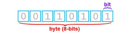
I receive 2 values, 1 and 213. Now these two numbers are actually stored as 8 binary bits. The values of those bits are 00000001 and 11010101 respectively (HERE is a convenient calculator). The value I want is the 16 bit int variable that results when these two are added together. ie I want the number represented by 0000000111010101; that would be 469. Sounds like I need to do some Arduino data type conversion.
I Googled around and asked one of my computer science friends, but there doesn't appear to be a ready made solution for this. I should point out that if you are reading the value directly from a serial port, you can just use parseInt(). My problem is that I am using an external library to get the sensor data and then need to combine the bytes afterward.
After some deliberation I acquired a list of ways I thought I could combine two 8-bit bytes into one 16- bit int (or short) variable. Some of these ways I have not pursued, but a few I have. I have tested them, and clocked the processing times for a few values on an Arduino Mega2560 r3.
Combination using bitRead(): 108 microseconds
This is the first method I thought of. It reads each bit in the byte and then copies it over to the int. This is not very efficient, but it does get the job done. It does take quite a bit more clock time than the other methods, but it is a rather intuitive approach.
This method is basically identical to the one above. I read conflicting arguments for whether it would be any slower or not. If it is, it is pretty negligible. Basically, instead of shifting the bits using a bit shift, I just multiply by 256. This is like if I wanted to shift the "1" in 10 to the 1000th place. I would multiply by 100 (10^2). In binary I want to shift it 8 places, so I multiply the variable by 2^8 or 256.
Conclusion
There are probably other methods of combing bytes into an int that I have not looked at. If so, post a link in the comments. That will only broaden the scope of this post. All of the methods here could be adapted to match a 32 bit long if necessary and could be put into an unsigned variable just as easily as a signed one. With that in mind, I will probably use the bit shift method from now on. It seems like the most elegant and efficient solution.
I hope this post helped someone out. If you want my script to check the clock times for yourself, find it HERE. It also might help if you're a little fuzzy on exactly what is going on. If something doesn't work for you, comment below, and I'll do my best to help you.
-Matthew
I receive 2 values, 1 and 213. Now these two numbers are actually stored as 8 binary bits. The values of those bits are 00000001 and 11010101 respectively (HERE is a convenient calculator). The value I want is the 16 bit int variable that results when these two are added together. ie I want the number represented by 0000000111010101; that would be 469. Sounds like I need to do some Arduino data type conversion.
I Googled around and asked one of my computer science friends, but there doesn't appear to be a ready made solution for this. I should point out that if you are reading the value directly from a serial port, you can just use parseInt(). My problem is that I am using an external library to get the sensor data and then need to combine the bytes afterward.
After some deliberation I acquired a list of ways I thought I could combine two 8-bit bytes into one 16- bit int (or short) variable. Some of these ways I have not pursued, but a few I have. I have tested them, and clocked the processing times for a few values on an Arduino Mega2560 r3.
Combination using bitRead(): 108 microseconds
This is the first method I thought of. It reads each bit in the byte and then copies it over to the int. This is not very efficient, but it does get the job done. It does take quite a bit more clock time than the other methods, but it is a rather intuitive approach.
int BitReadCombine( unsigned int x_high, unsigned int x_low)
{
int x;
for( int t = 7; t >= 0; t--)
{
bitWrite(x, t, bitRead(x_low, t));
}
for( int t = 7; t >= 0; t--)
{
bitWrite(x, t + 8, bitRead(x_high, t));
}
return x;
}
Combination using bit shifting: 4 microseconds
In this method, a bit shift operator is applied to move the high byte into the correct position in the final int. This, to me, is the most elegant solution. I don't know that you will find anything much faster. Note that the micros() function has a resolution of 4, so measuring something like this directly is a little difficult. Code modified from HERE.
int BitShiftCombine( unsigned char x_high, unsigned char x_low)Combination using multiplication: 4 microseconds
{
int combined;
combined = x_high; //send x_high to rightmost 8 bits
combined = combined<<8; //shift x_high over to leftmost 8 bits
combined |= x_low; //logical OR keeps x_high intact in combined and fills in //rightmost 8 bits
return combined;
}
This method is basically identical to the one above. I read conflicting arguments for whether it would be any slower or not. If it is, it is pretty negligible. Basically, instead of shifting the bits using a bit shift, I just multiply by 256. This is like if I wanted to shift the "1" in 10 to the 1000th place. I would multiply by 100 (10^2). In binary I want to shift it 8 places, so I multiply the variable by 2^8 or 256.
int MultiplicationCombine(unsigned int x_high, unsigned int x_low)
{
int combined;
combined = x_high;
combined = combined*256;
combined |= x_low;
return combined;
}
Other possibilities
It was suggested to me that I should use strings. This seems like a rather roundabout way of getting there, but I would think it would work. You need to combine each byte into a binary string and then concatenate them by adding them together. Then you can convert them back to an int and you're good to go. This could be accomplished several ways with one being the itoa and atoi functions.
Edit: Thanks to Nigel Parker for adding another method and elaborating calculating the speed of each more precisely. In his comment he details how to use the union constructor to combine bytes into different data types. I have saved his code in a sketch available HERE. He notes that this method can be faster than any of the previous methods mentioned when used correctly.
Edit: Thanks to Nigel Parker for adding another method and elaborating calculating the speed of each more precisely. In his comment he details how to use the union constructor to combine bytes into different data types. I have saved his code in a sketch available HERE. He notes that this method can be faster than any of the previous methods mentioned when used correctly.
Conclusion
There are probably other methods of combing bytes into an int that I have not looked at. If so, post a link in the comments. That will only broaden the scope of this post. All of the methods here could be adapted to match a 32 bit long if necessary and could be put into an unsigned variable just as easily as a signed one. With that in mind, I will probably use the bit shift method from now on. It seems like the most elegant and efficient solution.
I hope this post helped someone out. If you want my script to check the clock times for yourself, find it HERE. It also might help if you're a little fuzzy on exactly what is going on. If something doesn't work for you, comment below, and I'll do my best to help you.
-Matthew
Subscribe to:
Posts (Atom)