Thursday, June 13, 2013

Serial Communication on a ATtiny85 with the SoftwareSerial Library.

"Serial is giving me errors on my ATtiny! What can I do?" We have a solution.

Serial communication is not difficult on an ATtiny thanks to the SoftwareSerial Library. While the ATtiny85 does not have the hardware of a "real" Arduino, it can still function in similar fashion. If you're just getting started with using an ATtiny, here are some resources you might need.

  • Information on programming them from High-Low Tech. You can also look back at my previous posts.
  • My nifty programming adapter. A few minutes of soldering made my life much easier.
  • My USBtinyISP is discussed in THIS post. It also makes life easier.
  • Previous posts on Running Servos and the NewPing Library on an ATtiny.
  • THIS previous post mentioning my USB to UART converter cable
Now we are ready to go. First things first, I am using Arduino 1.0.4. The SoftwareSerial Library is included as a default library, so there is no reason to get a 3rd party library.


Step One: Wire it up. With my USB to UART cable it is as follows.
  • Black: Ground
  • Green: Tx (using Tx as pin 4)
  • White: Rx (using Rx as pin 3)
  • Red: 5v (this is optional if you have an external power supply)
Connect an LED with appropriate resistor to pin 1.

Step Two: Ensure that your ATtiny is burned to run at 8MHz. Now load THIS sketch onto the ATtiny. Note that parseInt() works with the SoftwareSerial Library.

Step Three: Open the Serial Monitor and set it to the correct Baud rate. To reset the ATtiny, bridge the reset pin to ground momentarily. When you see the connected message, enter an integer and count the flashes.

That's all there is to it. I you don't have a USB UART cable, this is easily adaptable to communication with another Arduino with a USB port. See THIS post for code. If you want to see a practical application of serial communication on an ATtiny85, check out my serial sonar controller HERE.

Hope this works for you all. As usual, if there are any questions, just let me know.
-Matthew

Tuesday, June 11, 2013

Multiple Simultaneous Serial Communications

As I mentioned in an earlier post I have an Arduino Mega with a broken USB to serial chip. With that in mind, I thought it would be useful to have an external USB to UART cable. Mine was $4 on Ebay. When it arrived I set to work ringing it out to make sure it worked. Here are the results.

Because my "broken" Arduino is still on my robot, I just used my working one. It is a supposedly identical Arduino Mega 2560 R3. As I played with this I realized that I could communicate with 2 ports simultaneously now (or 3 if I broke out my Bluetooth again). Why is this useful? It's not at the moment. This is really pretty simple, so this will be a short post.

Step One: Wire it up. With my cable it is as follows.

  • Black: Ground
  • Green: Tx (using Tx1 pin 18)
  • White: Rx (using Rx1 pin 19)
  • Red: 5v (this is optional if you have an external power supply).
It is worth noting that my cable does not allow for auto reset. This means that it is pretty difficult to load new programs to the Arduino with the default bootloader. 

Step Two: Load program on Arduino. This very simple. HERE is my example. When you're done, leave the USB plugged in.

Step Three: Open the Serial Monitors and watch for the messages. You will either need to use another program like Tera Term as mentioned in THIS post, or you can open two windows of the Arduino IDE.

That's all there is to it. Now you can communicate with the computer via two serial ports "simultaneously." If you need more information on Serial communications check out THIS post. I also have a post on I2C communication as well as Bluetooth.

-Matthew

Friday, June 7, 2013

Arduino Bluetooth with a HC-06 and JY-MCU

With the arrival of my Bluetooth module I decided to give wireless communication another try. I'm glad I did. Setting up my Bluetooth module for wireless communication took less than an hour. While I have not explored it very in depth yet, I can see myself getting some use from this module. It becomes a generic wireless COM port. I have even read about uploading sketches via Bluetooth if you use a custom bootloader. I will probably never delve into that, but let's get started with the basics.

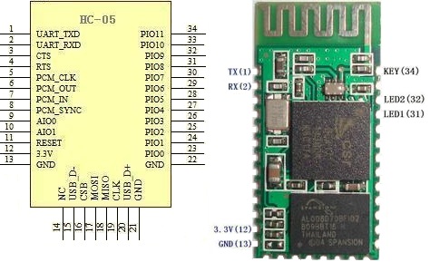
When I first ordered my Bluetooth module, I got a "Bluetooth Serial Transceiver Module Base Board with Enable function For Arduino" from Ebay. I payed a few dollars for it only to realize when I got it that the board was merely a breakout (called a JY-MCU) for another board. Another purchase later, and I had all the things I needed to get going. I got an HC-06 (aka "New Mini 3.3V wireless Bluetooth Transceiver Slave Module Serial Port 30ft TTL"). There is also an HC-05 which apparently is very similar (it seems to share the same pinout).


HC-05 pinout
First things first, I soldered my HC-05 onto the JY-MCU. These can be purchased already soldered for less than $10, but the soldering was good practice. I held the module in place with double sided tape and a piece of tape around the end while I soldered it. The contacts aren't too small, but you will need a decent soldering iron with a small tip.
My impressive soldering


Next I wired it up. This is the point where I began calling on the collective knowledge of the internet. Follow THIS Instructable. With a few changes, it is what I did. For the voltage divider I used a 2.2k Ohm and a 1k Ohm + 100 Ohm resistor. It worked fine. I checked it with the volt meter and it came out to about 3.1v. HERE is the voltage divider calculator I used. Be sure you use that on the Bluetooth Rx/ Arduino Tx side or else you could fry your Bluetooth module. The ATmega 2560 will accept 3.3v so the Arduino Rx is fine by itself (sort of. I wouldn't put this on anything too important, but worst you will get false data). Someday I'll get a real logic level converter. For convenience, I used the Serial1 pins on my Arduino Mega 2560.

Now you need to load a test sketch onto your Arduino. I used the one on the Instructable (with Serial changed to Serial1). To do this you will probably need to unplug the Arduino Rx pin. Should we have loaded the program before wiring like the Instructable said? Probably. Oh well. Take this opportunity to double check all wiring and ring them out with a volt meter.

Now we need to connect the HC-06 Bluetooth module to the computer. I am running Windows 7, and this took about 3 minutes. The steps are on the Instructable, but I would feel bad if I didn't post all the screenshots that I took. Power up your Bluetooth module and follow the steps below.

1) Find the Bluetooth Icon in the bottom right hand portion of the screen. Right Click and Select "Add a Device." My device was called linvor. Whatever floats their Chinese boat. The password for mine was 1234. If that doesn't work, try 0000.


2) Go to Devices and Printers and see if it appears. Wait for Windows to install all necessary drivers. note what COM port it is using. Mine uses two apparently.. Oh well. Not worth the energy to worry about it.


3) Download a terminal emulator program. "Can't I just use the Serial Monitor???" No. Only one device can use a serial port at a time. That is why the Serial Monitor shuts down when you upload a sketch. "Then what should I use???" Well I used Tera Term like the Instructable said because it was the least confusing to a simple mind like me. PuTTy and RealTerm are probably more popular choices. I haven't explored them. I'll assume you use Tera Term.

4) Connect to the module in Tera Term. This is super simple. Select the right COM port.


5) Bask in the beauty of the numbers streaming by. 


This took all of an hour for me. I was astonished at how painless it was, especially compared to my struggles with the nRF24L01+. I am not sure what I will do with it now (I have some ideas). I hope you all have the same success I did. If you need the sample sketches for some reason, they are HERE.

Best of luck,
-Matthew