In this post I will detail how to easily use OpenCV with an Arduino to detect and track a face. There are many methods out there, but this method gives you the best OpenCV GUIs that I have seen. Vision processing is never simple, but I think you will be pleasantly surprised.
First things first, I would probably get a lot more Google hits if my title said install OpenCV on Arduino. Many wayward Arduino users have traveled that road only to feel a little foolish when they realize just how impossible that is. An Arduino doesn't come close to cutting it in terms of processing power. There is a project porting OpenCV to a rasberrypi, but that is a different post. What we will be doing is using a computer to process video from a connected camera and then send the useful data to an Arduino in the form of (x,y) coordinates via serial. This is cool because it means that your Arduino can be connected via
Bluetooth or USB and can do other things while the computer handles the heavy lifting.
The program that I will be using is called
myrobotlab (MRL). I go into more detail in my
Intro to myrobotlab post, but basically it is opensource, free, and in active development. When I set out to find an easy, GUI enabled OpenCV platform, this is what I found. While I have not done a full out comparison to ROS or RoboRealm, my general impression is that ROS is quite a bit more complicated, and RoboRealm is quite a bit more expensive (MRL is free). Regardless, you want a simple OpenCV, Arduino system. Let's go get one.
First you need to install myrobotlab. See the
Quick Start section for instructions. Make sure you get the right version of Java. I seem to remember having some problems with that. If you do, post a comment or ask GroG on the site. I'd also recommend that you go ahead and create an account on myrobotlab.org. If you need help or have a question, that's where you need to be.
Next open MRL by clicking on the batch file and go to the runtime tab. Here you'll find a list of all the
services MRL currently has to offer. Go ahead and scroll down to OpenCV. Right click on it to download and install it.
Then right click on it again and click start. It will want you to give it a name. Call it whatever you want. You do this so you can have multiple instances of the same service open if you want to.
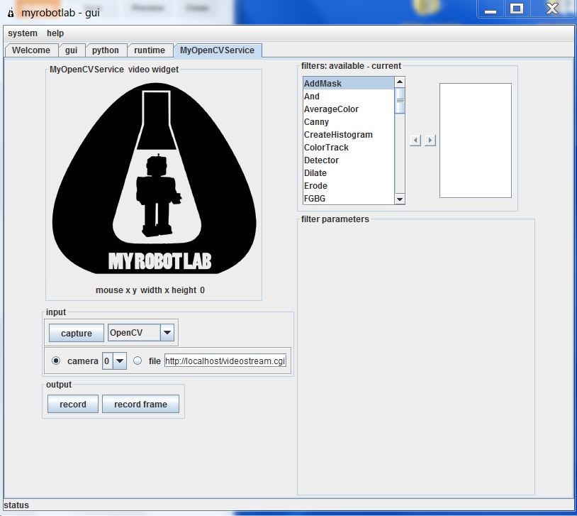
Now you are come to the OpenCV GUI. It will default to camera 0. If you have multiple cameras connected, this might not be the one you want. Click capture to see what camera you have selected, and find the one you want.
Now we need to add our filters. First you need to scroll through and select PyramidDown. Either right click and add or select and hit the right arrow. Give it whatever name you want. PyramidDown makes the video smaller (you'll see). FaceDetect is pretty processor heavy, and unless you have a monster work station you'll want to use it. It will actually increase performance.
Next add the FaceDetect filter. Now click capture and go to town. You should see video in the box and a box drawn around any face. This is a good time to play around. The majority of the filters can be accessed through the GUI. See what filters help you isolate the face(or whatever you are trying to track). Try multiple PyramidDown filters or an InRange filter. Also note that if you right click in the display window, it will give you the coordinates in pixels. This is useful behavior.
Now I hit you with the bait and switch. It's not nice and GUI all the way to the end. Reason being, you need another service (the serial service) to actually get the data from your nice OpenCV box to your Arduino board. This requires you to use the python service.
The code really isn't that bad. I knew no python when I started working with myrobotlab. I still know very little, but I have pieced stuff together well enough from
example sketches. You can look at the sketch below, but I would recommend you download it
HERE.
# This code creates an opencv service and tracks a face.# It thens finds the center of the face and converts the position to a scale of 1-100# This information is then sent via serial service to any receiving device
# If the script needs to be restarted, completely close MRL and reopen it.# 8/27/13
import time
from java.lang import Stringfrom java.lang import Classfrom java.awt import Rectanglefrom org.myrobotlab.service import Runtimefrom org.myrobotlab.service import OpenCVfrom org.myrobotlab.opencv import OpenCVDatafrom com.googlecode.javacv.cpp.opencv_core import CvPoint;from org.myrobotlab.service import OpenCV
# create or get a handle to an OpenCV serviceopencv = Runtime.createAndStart("opencv","OpenCV")
# Convert the video to Black and Whiteopencv.addFilter("Gray1", "Gray") # Sometimes gray seems to help# reduce the size - face tracking doesn't need much detail. The smaller the fasteropencv.addFilter("PyramidDown1", "PyramidDown")# add the face detect filteropencv.addFilter("FaceDetect1", "FaceDetect")
#create a Serial service named serialserial = Runtime.createAndStart("serial","Serial")
# This function is called every time the OpenCV service has data available.# This will depend on the framerate of the video, but will probably be# somewhere around 15 times a second.def input(): global x global y global sposx global sposy global posx global posy
# Get OpenCV data opencvData = msg_opencv_publishOpenCVData.data[0]
if (opencvData.getBoundingBoxArray().size() > 0) : # If the box surrounding a face exists rect = opencvData.getBoundingBoxArray().get(0) # Store the information in rect posx = rect.x # Get the x position of the corner posy = rect.y # Get the y position of the corner
w = rect.width # Get the width h = rect.height # Get the height sposx = (w/2) sposy = (h/2) # Get the x and y of the center in pixels. Origin is in top left corner x = (posx + sposx)
y = (posy + sposy)
# Convert x,y pixels to (x,y) coordinates from top left. # Note that 320 and 4240 will need to be changed if another pyramid down is used # It may also need to be changed depending on your cameras specifications. # This gets the position in a scale from 1, 100 x = int(translate(x, 1, 320, 1, 100)); # translate() works the same way the Arduino map() function would y = int(translate(y, 1, 240, 1, 100)); print 'x: ' , x # print x to the python readout print 'y: ' , y # print y to the python readout #write a series of bytes to the serial port serial.write(250) # pan code serial.write(x) # x coordinate serial.write(251) # tilt code serial.write(y) # y coordinate
#connect to a serial port COM15 57600 bitrate 8 data bits 1 stop bit 0 parity#This is what you want for an Arduino. Change the COM port to the one you are using.serial.connect("COM15", 57600, 8, 1, 0)#sometimes its important to wait a little for hardware to get readysleep(1) # Note that this is 1 full second.
# create a message route from opencv to python so we can see the coordinate locationsopencv.addListener("publishOpenCVData", python.name, "input");
# Start capturing videoopencv.capture() # Add a 1 inside the parenthesis to use camera 1
# Create function to scale values. Mimics Arduino map() function.def translate(value, leftMin, leftMax, rightMin, rightMax): # Figure out how 'wide' each range is leftSpan = leftMax - leftMin rightSpan = rightMax - rightMin
# Convert the left range into a 0-1 range (float) valueScaled = float(value - leftMin) / float(leftSpan)
# Convert the 0-1 range into a value in the right range. return rightMin + (valueScaled * rightSpan)
Copy that into the python window and you're almost done. Towards the end you need to change the COM port to the one you are using. Below that, you will see opencv.capture(). If you are using a camera other than camera 0, put that number in the parenthesis.
Now connect your Arduino and click execute. You will see several readouts in the java window. The last one you should see should say
[opencv_videoProcessor] INFO org.myrobotlab.opencv.VideoProcessor - using com.googlecode.javacv.OpenCVFrameGrabber
That means you made it to the bottom of the script and you are getting video.
This is what is happening. The OpenCV service applies 3 filters: Gray, PyramidDown, and FaceDetect. It gets a box around the face and passes the coordinates in pixels to the python service. The python service finds the center of the box and the converts the pixel coordinates to a scale of 1-100 with the origin in the top left with positive down and to the right. The python service then passes the coordinates to the Serial service which connects to your COM port and begins sending x, y values across. It sends an identifier, then the value in the order below. Both the identifier and the coordinate are 1 byte in length.
- 250
- x coordinate
- 251
- y coordinate
What you do with those values on the Arduino side is up to you. That is why I used the serial service. It enables you to plug this system up to an existing Arduino project or any existing Arduino sketch and get vision processing data with nothing more that a Serial.read() and some if statements. Best of all, it is all in Arduino C, so anyone that has learned to program on an Arduino (like myself) can deal with the complicated stuff in a language they already know using the libraries that they already know.
I chose to make a pan-tilt camera mount that follows people, but like I said above, what you do with those (x,y) coordinates is really up to you. If you need help with serial communication, see my posts
HERE and
HERE. If you just want my pan-tilt Arduino code get it
HERE. If you want the detailed description... wait until I write that post.
That's all I have. I plan on doing more specific examples in the future. For now, this should get you started. For more examples look at my labels. The one's labeled myrobotlab or vision processing will be the ones to check out.
I hope this is of use to someone. I really do think myrobotlab is one of the best free, simple GUI system for OpenCV out there. It is fairly easy to use, and the support is great (just post on the site and ask for help). When I began using it, there was no serial service. I asked for one, and within a week GroG had added one.Who could ask for more?
Goodluck! May your frame rates always be high and your visions always be processed.
-Matthew
 Not a whole lot of information was given with this purchase, but what the seller offered I saved for posterity below.